This Simple Light Activated Alarm Circuit is like very sharp nightlight.
It have small part called LDR which work like a tiny eye.
When light goes away fast like someone is moving near circuit it make sound or light happen to warn us.
It also uses other parts like transistors, resistors, capacitors to make it all work nice.
Circuit Working:
Parts List:
| Component | Description | Quantity |
|---|---|---|
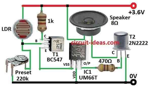
| Resistors | 1k 1/4 watt | 1 |
| 470Ω 1/4 watt | 1 | |
| Preset 220k | 1 | |
| LDR | 1 | |
| Semiconductors | IC UM66T | 1 |
| Transistor BC547 | 1 | |
| Transistor 2N2222 | 1 | |
| Speaker 8Ω | 1 |
This easy music light alarm circuit need only 7 parts like LDR and 3.6V battery or 3 pcs 1.2V chargeable battery.
It uses famous IC UM66 chip to make nice music sound for wake up alarm.
We must know LDR have big resistance which is up to 1M but when light come its resistance go down fast.
In this circuit we can turn the 220k preset to change how much light is needed to start an alarm.
When light hit LDR transistor T1 start working and give power to UM66 music chip.
Then transistor T2 makes sound louder and sends to 8 ohm speaker.
UM66 chip have many types each gives different song.
We can use 2 normal 1.5V battery but better is 3 x 1.2V NiCad or NiMH battery because they can charge again.
Formulas:
This light alarm circuit uses LDR to check light change.
When LDR sees less light it tell transistor to turn ON and then buzzer or speaker makes sound.
There is small formula for this:
Vout = Vin × (R2 / (R1 + R2))
where:
- Vout is output voltage
- Vin is 3.6V battery power
- R1 is LDR resistance
- R2 is 1k resistor
This formula helps find voltage on 1k resistor and that voltage is what turn ON the transistor.
If LDR resistance go high means its dark then voltage on 1k resistor go low and so transistor may not turn ON.
This is just small idea of real circuit but the real one also have transistor and speaker to make sound louder when light change happen.
How to Build:
To build a Simple Light Activated Alarm Circuit follow the below mentioned steps:
How to Connect the Circuit:
- Join battery positive (+) to PCB positive power line and negative (-) to ground.
- Take pin 1 of UM66 chip and connect it to positive line through emitter of BC547 transistor.
- Connect pin 2 ground of UM66 to negative line.
- Connect one side of speaker to collector of T2 2N2222 transistor and other side of speaker to positive line.
- Connect emitter of T2 to negative line.
- Join pin 3 of UM66 to base of T2 using a 470 ohm resistor.
- Connect emitter of T1 to negative line through a 220k resistor.
- Join point where LDR and 220k resistor meet to base of T1 BC547.
- Turn the 220k preset to adjust how sensitive the light sensor is.
Testing the Circuit:
- Shine some light on LDR and if everything is okay then speaker will make sound.
- Use preset knob to change how much light needed to start an alarm.
Important Note:
- Be careful with plus and minus sides of battery and parts the wrong connection can damage the circuit.
- Work slow and safe when doing electrical things.
Conclusion:
This Simple Light Activated Alarm Circuit is easy but works good and it turn ON the alarm or other device when light changes.
It uses LDR as sensor to see light going up or down.
We can use this circuit for many things like home security, auto lights and more as it is useful and can do many jobs.
Leave a Reply