This NiMH Battery Charger Circuit is like special water can for NiMH batteries which are the same batteries inside camera, toy and other devices.
Normal charger maybe not be so good for these batteries but this NiMH charger circuit give just right power and make battery work good and last long time.
Circuit Working:
Parts List:
| Type | Description | Quantity |
|---|---|---|
| Resistors | 10Ω 1/4 watt | 1 |
| 1.5k 1/4 watt | 1 | |
| Capacitors | Electrolytic 470µF 50V | 2 |
| Semiconductors | Transistor TIP127 | 1 |
| Bridge Rectifier 1N4007 | 4 | |
| LED Green 5mm 20mA | 1 | |
| Transformer 0V to 18V 1Amp | 1 | |
| NiMH Battery 9V to 12V | 1 |
This charger gives 140 mA current so that the battery charges fast.
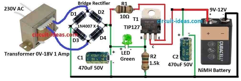
Power part have 0 to 18V AC, 1 amp transformer, four diodes D1 to D4 to make DC and one big capacitor C1 to smooth the power.
Charging current is controlled by R1, R2 and one PNP transistor called TIP127 T1.
R1 keep the current at 140 mA.
LED and R2 help control T1 by managing current going to its base.
LED make around 2.6V drop at base of T1 and T1s base emitter drop is around 1.2V.
So current through R1 is (2.6 – 1.2) ÷ 10 ohms = 0.14 A or 140 mA.
LED also show charging and it turn ON only when battery is connected and power is OK.
Formulas:
When making charger circuit for NiMH battery we should remember some easy formula and important things:
How to Find Charging Current (Icharge):
Charging current is also called C rate is small part of battery size (capacity).
Normally NiMH battery charge with C/10 to C/20.
Use this formula:
Icharge = C / 10 to C / 20
where:
- C is battery size in Ah ampere hour
How to Find Resistor R1 for limit charging current:
Put resistor R1 in series with battery to stop too much current.
Use ohms law:
R1 = (Vsupply − Vbattery) / Icharge
where:
- Vsupply is voltage after rectifier and filter of DC voltage
- Vbattery is normal battery voltage
- Icharge is current we want for charging
How to Choose Charging Voltage:
NiMH battery charge voltage is 1.4V to 1.5V per cell.
If battery have many cells in series then we can use formula:
Vcharge = N × Vcell
where:
- N is the number of cells
- Vcell is the voltage for one cell like 1.4V to 1.5V
Notes:
These formulas give basic idea for NiMH charger circuit.
We may need to change values if battery or components are different.
Always check battery while charging and do not overcharge or let it get too hot.
How to Build:
To build a NiMH Battery Charger Circuit follow the below mentioned connections steps:
Transformer and Rectifier:
- Connect transformer to input of bridge rectifier.
- Transformer should have center tap output and should connect center tap to negative side of bridge rectifier.
- Positive and negative output of bridge is connected to smoothing capacitor C1 with positive to positive and negative to negative.
Current Control:
- Put resistor R1 in series with positive output from rectifier.
This limits current to 140mA. - Connect resistor R2 and LED in series from base of TIP127 transistor T1 to positive supply.
R2 helps control base current of transistor.
Transistor and Charging:
- Connect emitter of transistor to positive output of rectifier through R1 and also connect with capacitor C1 and ground.
- Collector of transistor connects to positive side of capacitor C2 and also to positive battery connector.
Charging Status:
- LED shows the charging status.
- It turns ON when battery is connected and input voltage is normal.
Final Assembly:
- Put all parts on circuit board and solder them properly.
Keep good spacing and insulation and especially near high voltage parts. - Use heat sink for transistor if it becomes hot while working.
- Before connecting the battery check all wires and parts.
- Then connect battery to output.
- If LED turns ON it means circuit is working good.
Note:
- Working with electricity is risky.
- Only do this if one is having some knowledge and skill about electronics
- If anyone is not sure then ask help from someone who knows electronics.
Conclusion:
A NiMH Battery Charger Circuit is made to charge NiMH batteries safely and in good way.
It usually have three main parts: Power supply part, Current control part and Charging status LED
This circuit checks the battery charge at the correct speed so it is not overcharge or gets damaged.
Leave a Reply