This article for Super Sensitive Intruder Alarm Circuit talks about very simple but strong intruder alarm circuit.
It is very sensitive.
These circuit is good for security.
They can catch very small intrusions.
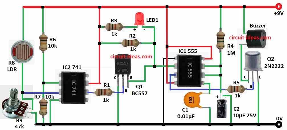
This circuit uses IC 741 op-amp and IC 555 timer to work.
It also use LDR (light sensor) as main part so it can feel small light changes.
Circuit Working:
Parts List:
| Component | Value/Type | Quantity |
|---|---|---|
| Resistors (All resistors are 1/4 watt unless specified) | ||
| 1k | 4 | |
| 1M | 1 | |
| 10k | 2 | |
| LDR | 1 | |
| Potentiometer 47k | 1 | |
| Capacitors | ||
| Ceramic 0.01µF | 1 | |
| Electrolytic 10µF/25V | 1 | |
| Semiconductors | ||
| IC 741, 555 | 1 each | |
| Transistor BC557 PNP | 1 | |
| Transistor 2N2222 NPN | 1 | |
| Buzzer | 1 | |
| LED any 5mm 20mA | 1 |
In this post alarm goes OFF even if intruder walk few meters away.
LDR and R9 potentiometer work like voltage divider.
LDR changes resistance when light change.
More light means less resistance.
This change makes voltage across R9 also change.
IC2 741 op-amp compare this voltage which is non-inverting input with fixed voltage from other resistors like inverting input.
If LDR voltage is higher then reference voltage then IC2 output goes high.
Then Q1 BC557 turns ON and send low pulse to pin 2 of IC1 555 timer.
IC1 work in monostable mode then it gives high output for some time to set by R4 and C2.
This high output turns ON the Q2 2N2222 which starts the buzzer.
Also LED1 turns ON to show intruder is detected.
Formulas with Calculations:
Below are simple calculations for Super Sensitive Intruder Alarm:
Voltage Divider Output:
V_LDR = (R9 / (R9 + R8)) × V_supply
where,
- R8 is the LDR resistance which changes with light
- R9 is the potentiometer
- V_supply is the power supply voltage
Monostable Output Time (555 Timer):
T = 1.1 × R4 × C2
where,
- R4 is the 1 meg ohm
- C2 is 10µF
T = 1.1 × 1,000,000 × 0.00001 = 11 seconds
So buzzer stays ON for 11 sec after trigger.
How to Build:
To build a Super Sensitive Intruder Alarm Circuit follow the below mentioned steps:
- Take all parts as shown in circuit diagram.
IC1 555 timer:
- Pin 1 connects to GND
- Pin 2 connects to emitter of Q1
- Pin 3 connects to base of Q2 through resistor R5
- Pin 4 & pin 8 connects to +9V
- Pin 5 goes to GND through capacitor C1
- Pin 6 & pin 7 connect with resistor R4 to +9V and capacitor C2 goes to GND
IC2 741 op-amp:
- Pin 2 which is the inverting pin goes between resistors R6 (+9V) and R7 (GND)
- Pin 3 which is the non-inverting pin goes between LDR (R8 to +9V) and pot (R9 to GND)
- Pin 4 connects GND
- Pin 6 connects to base of Q1 through resistor R1
- Pin 7 connects to +9V
- LED1 + R3 connects between pin 7 of IC2 and pin 2 of IC1
- R2 connects between pin 7 of IC2 and pin 2 of IC1
Q1 BC557 transistor:
- Collector connects to GND
- Base goes to pin 6 goes to IC2
- Emitter goes to pin 2 of IC1
Q2 2N2222 transistor:
- Collector connects to one leg of buzzer
- Other leg of buzzer goes to +9V
- Base goes to pin 3 of IC1
- Emitter connects to GND
Conclusion:
This Super Sensitive Intruder Alarm Circuit is easy and works well.
It uses LDR to catch small light changes and is good for doors, windows etc.
We can change potentiometer to make it more or less sensitive.
It is good project to learn electronics and improve home security.
Leave a Reply