This article is for Women Safety Alarm Circuit using GPS GSM NodeMCU.
It uses NodeMCU ESP8266 board as brain.
GPS module give location.
GSM module send SMS to family.
One push button used to send alert.
Circuit Coding:
#include <SoftwareSerial.h>
#include <TinyGPS.h>

SoftwareSerial gpsSerial(D6, D5);
SoftwareSerial gsmSerial(D3, D2);
TinyGPS gps;

float lat, lon;
int buttonPin = D1;

void setup() {
pinMode(buttonPin, INPUT_PULLUP);
Serial.begin(9600);
gpsSerial.begin(9600);
gsmSerial.begin(9600);
delay(1000);
gsmSerial.println("AT");
delay(1000);
gsmSerial.println("AT+CMGF=1");
delay(1000);
}

void loop() {
while (gpsSerial.available()) {
gps.encode(gpsSerial.read());
gps.f_get_position(&lat, &lon);
}

if (digitalRead(buttonPin) == LOW) {
sendLocationSMS(lat, lon);
delay(10000);
}
}

void sendLocationSMS(float lat, float lon) {
gsmSerial.println("AT+CMGF=1");
delay(500);
gsmSerial.println("AT+CMGS="+911234567890"");
delay(500);
gsmSerial.print("I am in danger. My Location: ");
gsmSerial.print("https://maps.google.com/?q=
");
gsmSerial.print(lat, 6);
gsmSerial.print(",");
gsmSerial.print(lon, 6);
gsmSerial.write(26);
delay(5000);
}
Coding Explanation:
- TinyGPS library read latitude and longitude.
- SoftwareSerial create extra serial pins for GPS and GSM.
- Button press send SMS with location link.
- Message send through GSM module.
- Google Maps link make easy to see location.
Circuit Working:
Parts List:
| Components | Quantity |
|---|---|
| NodeMCU ESP8266 Board | 1 |
| GPS Module (NEO-6M) | 1 |
| GSM Module (SIM800L or SIM900) | 1 |
| Tactile Switch | 1 |
| USB Cable or Battery (5V) | 1 |
NodeMCU ESP8266 is a main controller controls GPS and GSM.
GPS module (NEO-6M) is connected to NodeMCU TX/RX pins.
Gives real-time latitude and longitude to NodeMCU.
GSM module is used to send SMS to stored phone number.
Push Button Tactile Switch when pressed sends signal to NodeMCU to start alert process.
Power Connections of GPS, GSM is powered from NodeMCU 3.3V and Vin pins and GND.
NodeMCU powered by USB or battery.
GPS keeps sending location to NodeMCU.
Button press is detected by NodeMCU.
NodeMCU collects GPS location.
NodeMCU sends SMS with location through GSM module.
Alert reaches family or emergency contacts.
How to Build:
To build a Women Safety Alarm Circuit using GPS GSM NodeMCU follow the below steps for connections:
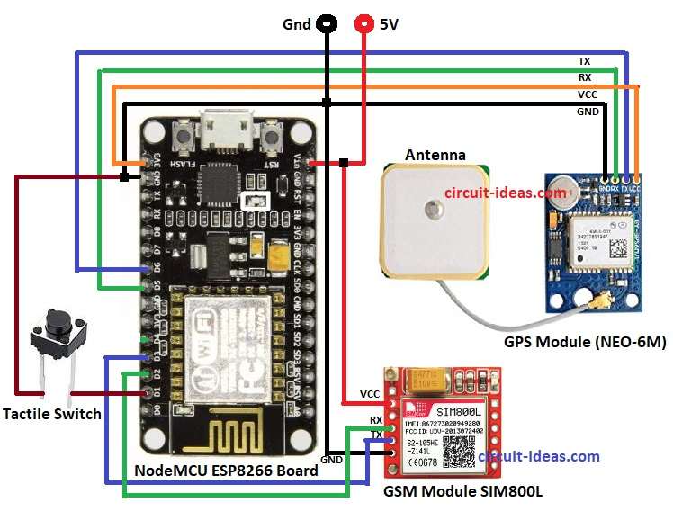
- Gather all the parts as shown in circuit diagram
- Connect GPS Module GND pin to NodeMCU GND pin
- Connect GPS Module RX pin to NodeMCU D5 pin
- Connect GPS Module TX pin to NodeMCU D6 pin
- Connect GPS Module VCC pin to NodeMCU 3.3V pin
- GSM Module Vcc pin connect to NodeMCU pin Vin or 5V
- GSM Module GND pin connect to NodeMCU pin GND
- GSM Module RX pin connect to NodeMCU pin D2
- GSM Module TX pin connect to NodeMCU pin D3
- Connect one end of tactile switch to NodeMCU D1 and other end to GND
Conclusion:
This small circuit helps women in danger.
One button press will send location SMS fast.
It is simple, low cost and portable.
References:
Women Safety Device using Arduino IJIPAR | Volume -13 | Issue 2 |
Leave a Reply