Power supply is required in many electronic circuits and most circuits need low DC voltage like 5V, 9V or 12V.
Normally a transformer is used to step down high AC voltage so however, transformer increases cost and size.
Therefore, many small circuits use transformerless power supply and this type of supply directly converts high AC voltage into low DC voltage without using a bulky transformer.
In this 9V DC Transformerless Power Supply Circuit, 220V AC input is converted into regulated 9V DC output.
The circuit uses capacitor dropper method to reduce voltage, after that rectifier diodes convert AC to DC and finally a Zener diode regulates the voltage.
However, transformerless circuits are not isolated from mains, so one should remember to handle it carefully.
Circuit Working:
Parts List:
| Components | Values | Quantity |
|---|---|---|
| Resistors (All resistors are 1/4 watt) | 47Ω, 220k | 1 each |
| 39k | 4 | |
| Capacitors | Ceramic / Polyester 1uF 400V or higher | 1 |
| Electrolytic 2.2uF 350V, 100uF 25V | 1 each | |
| Zener Diode 9.1V | 1 | |
| Bridge rectifier diodes 1N4007 1000V 1A | 4 | |
| Fuse 0.5A | 1 |
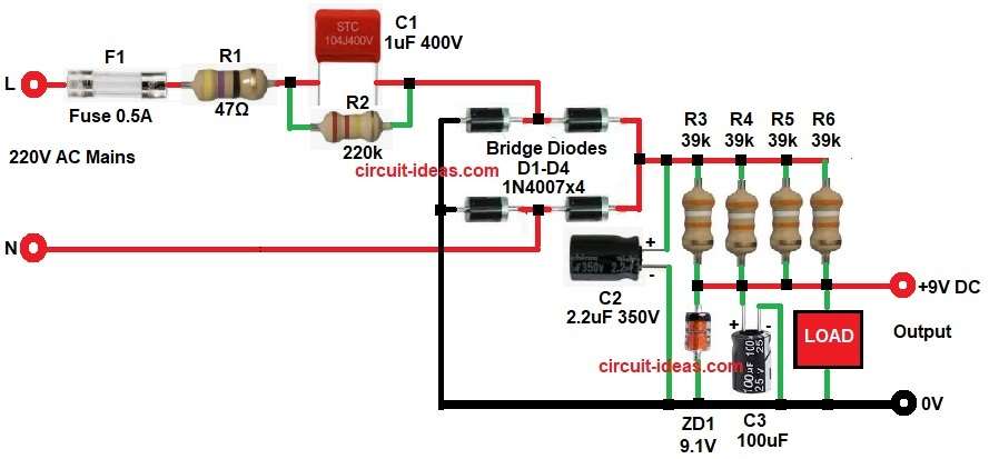
In the above circuit, L means Live wire which carries high voltage from AC mains supply and N means Neutral wire which returns current back to the power source.
The 220V AC enters the circuit through fuse F1 and this fuse protects the circuit from overcurrent and short circuit.
Then resistor R1 and capacitor C1 act as voltage dropping network, capacitor C1 limits the current coming from AC mains and this method is called capacitive dropping.
Next, resistor R2 is connected in parallel with capacitor C1 and this resistor works as discharge resistor which discharges the capacitor when power is turned OFF.
After that AC signal enters the bridge rectifier formed by diodes D1-D4, the bridge rectifier converts AC voltage into pulsating DC voltage.
Then capacitor C2 filters the rectified voltage and it reduces ripple and smooths the DC output.
After filtering the resistors R3, R4, R5 and R6 help in current distribution and limiting.
Next, Zener diode ZD1 regulates the voltage and this Zener diode keeps output voltage fixed around 9.1V.
Finally, capacitor C3 provides additional filtering and therefore a stable 9V DC output appears across the load.
How to Build:
To build a 9V DC Transformerless Power Supply Circuit following are the steps one need to follow:
- First, gather all the circuit components as in diagram above.
- Then connect AC phase line to fuse F1 input one end.
- Connect fuse output other end to resistor R1.
- Connect resistor R1 output in parallel to capacitor C1.
- Connect capacitor C1 output to bridge rectifier AC input terminals.
- Connect bridge rectifier positive output to capacitor C2 positive terminal.
- Connect bridge rectifier negative output to ground line.
- Connect resistors R3, R4, R5 and R6 in parallel between diodes positive line and 9V output line.
- Connect Zener diode ZD1 cathode to 9V output and anode to GND.
- Connect capacitor C3 positive end to 9V output line and negative to GND.
- Finally, connect load across 9V output and ground
Warning Note:
- This circuit works directly with 220V AC mains, touching circuit can give electric shock.
- Do not touch the circuit when power is ON because high voltage is present in the circuit.
- Transformer is not used in this circuit, so output is not isolated from AC mains.
- Use proper insulation while building this circuit and keep the circuit inside a plastic box.
- This power supply is only for low current circuits, do not use for heavy load devices.
- Always disconnect AC supply before repairing or testing the circuit.
- Beginner users should take help from experienced person before building this circuit.
- Use fuse for safety protection as fuse prevents damage during short circuit.
Conclusion:
9V DC Transformerless Power Supply Circuit is simple and is with low cost, as it removes the need for heavy transformer, therefore the circuit becomes small and compact.
This circuit can provide regulated 9V DC for low current electronic devices so it is useful for small sensors, LED circuits and microcontroller projects.
However, this circuit is directly connected to AC mains, therefore, it is dangerous if touched while powered, proper insulation and safety precautions are necessary.
Thus, transformerless power supply is good for low power applications but must be used carefully.
Leave a Reply