Make lights move with music because this music-controlled 220V light circuit project helps control lights using musical sound.
First, plug it into a normal power socket and then, the smart components inside make the light blink with the music beat.
Additionally, it uses a microphone to detect sound and meanwhile, a signal booster strengthens the signal, and a special switch controls the light’s behavior.
Circuit Working:
Parts List:
| Components | Values | Quantity |
|---|---|---|
| Resistors (All resistors are 1/4 watt unless specified) | R1 560k 1W | 1 |
| R2, R3 15k | 2 | |
| R4 33k | 1 | |
| R5, R6, R9 1k | 3 | |
| R7 18k | 1 | |
| R8 560Ω | 1 | |
| R10, R11, R12 100Ω | 3 | |
| Potentiometer VR1, VR2, VR3 5k | 3 | |
| Capacitors | C1, C8, C10, C12 0.047µF 630V Ceramic | 4 |
| C2 0.33µF 400V Ceramic | 1 | |
| C3 1000µF 16V Electrolytic | 1 | |
| C4 100µF 16V Electrolytic | 1 | |
| C5 0.1µF Ceramic | 1 | |
| C6 25µF 6V Electrolytic | 1 | |
| C7 1µF 16V Electrolytic | 1 | |
| C9 22µF 16V Electrolytic | 1 | |
| C11 47µF 16V Electrolytic | 1 | |
| Semiconductors | Transistor T1, T2 BC547 | 2 |
| Triac T3, T4, T5 BT136 | 3 | |
| Diode D1, D2 1N4004 | 2 | |
| Zener Diode D3 12V 1W | 1 | |
| Microphone Electret MIC Standard | 1 | |
| Switch SA, SB DPDT Switch | 1 | |
| Fuse F1, F2 100mA | 2 | |
| Coil L1 40µH 6A | 1 | |
| Bulb B1, B2, B3 220V Bulb | 3 |
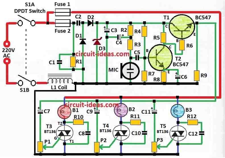
To begin with, this design shows how to make sound control light circuit.
Here, light brightness go up and down with music sound from microphone; also, people use this circuit for disco, party or bar to make fun blinking lights with music.
Before, old method connect light directly to speaker, but this is not good because loud sound can damage speaker or light.
So, this new circuit use microphone to hear sound and not connect direct to speaker, therefore it is more safe.
Also, circuit has two parts: one power supply with microphone amplifier and another light control section.
Then, capacitors C2 and C3 reduce power voltage like divider; also, diodes D1 and D2 change AC into DC using only positive side, while L1 and C1 stop voltage spikes.
Furthermore, use only 2-pin microphone and do not use 3-pin microphone; also, be very careful because circuit works with high voltage and current, so all parts must be strong for safety.
Moreover, use plastic knobs and plastic shafts for P1, P2 and P3 controls and microphone should connect with shielded wire.
In addition, all wires going to main power or light must have heat shrink tube cover, circuit box should be plastic and no metal part should stay outside.
Finally, triac heatsinks carry main line power, so there is no safety isolation; also, each triac can handle maximum 400W only, therefore more power can damage it.
Formula:
To make a 220V light move with music, we need to convert the music sound into a control signal and then, this signal can turn the light ON/OFF or adjust its brightness according to the music beat or loud sound.
Generally, we use something called an envelope detector, which is also known as a level detector.
In addition, this circuit checks the power level of the audio signal over time.
Also, the AC signal power can be expressed using this formula:
P(t) = V(t)2 / R
where:
- V(t) is sound voltage at that moment
- R is resistance in the circuit
Here, we use capacitor C to smooth signal and turn it from fast AC to slow DC this help control light better.
The speed of this smoothing depend on formula: τ = RC, which tell how fast signal follow music change.
Also, this method is basic way to build music control light using 220V, but one can change things based on what it needs.
How to Build:
To build a Simple Music Controlled 220V Light Circuit follow the below mentioned steps:
Get All Parts:
- First, gather all the required parts according to the circuit diagram, including resistors, capacitors, diodes, electret microphone, triacs, power supply, wires and potentiometers.
Build Power Part:
- Next, connect electret mic amplifier, capacitors C2 and C3, diodes D1 and D2, also L1 and C1 like in circuit picture; also be sure good isolation and use strong parts that can handle high voltage and current.
Build Light Control Part:
- Then connect triacs and potentiometers P1, P2, P3 same like in diagram and use only plastic knob and plastic shaft on potentiometer for safety.
Connect Microphone:
- After that, use protected shielded wire to connect mic to circuit and check with the connection are tight and grounded good.
Connect Power and Lights:
- Use heat shrink tubing to cover all wires connected to the power supply and lights and also, ensure that no metal parts are exposed outside the box, as this can be dangerous.
Test and Fix Problems:
- Turn ON the power and test the circuit and turn knobs to see if lights blink with music.
- Also, if something is not right than check and fix it.
Put Circuit in Box:
- Put everything inside a plastic box to keep it safe and ensure no metal parts are exposed, in addition, fix all components tightly.
Be Very Careful:
- Triac heatsinks may carry high voltage, which can be very dangerous; therefore, always check the isolation between the power line and the circuit.
- Additionally, each triac should not handle more than 400W and if it exceeds this limit, it may get damaged.
Test One More Time:
- Now, check again if all circuit parts are working good and safe.
Install Final Place:
- Then fix the circuit at the location where needed and check if there are no danger around.
Important Note:
- Lastly, always follow safety rules and carefully check the circuit diagram.
- If we are unsure about electronics, ask someone knowledgeable, such as an electrician or technician.
Conclusion:
To conclude, Simple Music Controlled 220V Light Circuit is useful system, which makes light blink or change with music which is very good for party, stage or show.
Also, it helps make good feeling by changing light brightness and color with sound, but be very careful this circuit uses high voltage.
Finally, always follow the safety rule when one need to build or use it.

Leave a Reply