LEDs mostly make light but they can also sense light!
Like a secret power, when light hits an LED in the right way, it generates a small amount of electricity; scientists call this phenomenon the photovoltaic effect, which works like a tiny solar panel.
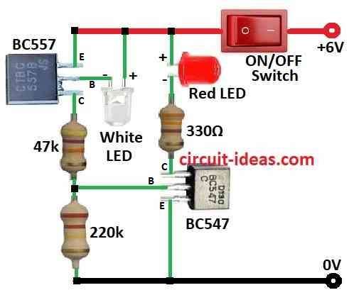
In this post for How to use an LED as a Light Detector Circuit we turn the LED backward means in reverse bias and this small electric signal shows how much light is around.
Circuit Working:
Parts List:
| Components | Values | Quantity |
|---|---|---|
| Resistors (All resistors are /14 watt) | 300Ω, 220k, 47k | 1 each |
| Semiconductors | ||
| Transistors BC547, BC557 | 1 each | |
| LED Red 5mm 20mA | 1 | |
| LED White (bright) | 1 | |
| Switch ON/OFF | 1 |
Most LEDs give off one color light but some can also detect light, as they are not as strong as real light sensors like solar cells or photoresistors.
Green LEDs can sense light a little but bright red LEDs work much better, also red ones are around 100 times more sensitive than green.
But there is a problem the signal they make is very weak, hence this circuit helps make that weak signal stronger so we can use the LED as a light detector.
However, most LEDs lack the sensitivity for this; therefore, we designed this circuit exclusively for high-brightness red LEDs..
Cool thing is this LED sees light only from its tip and so it is great for things like solar trackers where light direction matters.
But it is not so good for general room light unless the light is really close.
Formulas:
Useful Formulas for LED Light Detector Circuit
Red LED as sensor:
When red LED gets light use ohms law to find current:
ILED = (Vsupply – VLED) / RLED
- Vsupply is the power supply like 6V
- VLED is the voltage drop across red LED
- RLED is the resistor in series with red LED
Same formula:
ILED = (Vsupply – VLED) / RLED
- VLED is the voltage drop of white LED
- RLED is the resistor in series with white LED
Make sure RLED keeps the current safe, typically between 10 to 20 mA for normal LEDs.
Base Resistor for Transistor:
To control base current IB use:
RB = (Vin – VBE) / IB
- Vin is the voltage to transistor base
- VBE is the base-emitter voltage which is around 0.7V for silicon transistor
- IB is the base current
To find IB use this formulas:
IB = IC / β
- IC is the collector current
- β (hFE) is the transistor gain
Final Notes:
These formulas help build and understand LED detector circuit using resistors, transistors, LEDs and switch.
Change resistor and part values based on our LED type, transistor details and how we want circuit to work, also always double check our calculations with real parts.
How to Build:
How to use an LED as a Light Detector Circuit follow the below mentioned steps:
- First, connect emitter of BC547 to ground, connect collector of BC547 to +6V supply through 330Ω resistor and red LED in series and then connect base of BC547 to point where 220kΩ and 47kΩ resistors meet.
- Next, connect collector of BC557 to 47kΩ resistor, connect base of BC557 to one leg of white LED and connect other leg of white LED to +6V.
- Also, connect emitter of BC557 to +6V.
- Now connect ON/OFF switch to +6V DC supply.
Note:
- Be careful when working with electronics and ask help from expert if not sure.
Conclusion:
In this How to use an LED as a Light Detector Circuit normal LEDs act like light sensors and they are not as strong as real sensors but with some help they can still work well.
Also, they sense light from one direction so they are good for things like solar trackers where direction of light is important.
Leave a Reply