This Adjustable 4 LED Flasher Circuit using Transistors is a simple and useful electronics project for beginners which uses two 2N2222 transistors, four LEDs, capacitors, resistors and one variable resistor for speed adjustment.
The main purpose of this circuit is to flash four LEDs in an alternating pattern, two LEDs glow first and then the other two LEDs glow and this process continues again and again.
Moreover, the circuit allows easy speed control, just by rotating the variable resistor, we can increase or decrease the flashing speed.
Therefore, this circuit is suitable for decoration lights, warning indicators, school projects and learning transistor switching circuits.
Circuit Working:
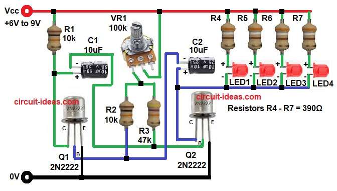
Parts List:
| Components | Values | Quantity |
|---|---|---|
| Resistors | 10k 1/4 watt | 2 |
| 47k 1/4 watt | 1 | |
| 390Ω 1/4 watt | 4 | |
| Potentiometer 100k | 1 | |
| Capacitors | Electrolytic 10uF 25V | 2 |
| Semiconductors | Transistors 2N2222 | 2 |
| Any standard 5mm LEDs | 4 | |
| Power Supply 6V to 9V DC | 1 |
The circuit works like astable multivibrator, as it has no stable state and it keep changing one state to another again and again.
First, when transistor Q1 is ON then transistor Q2 stays OFF and at this time the LEDs is on one side glow.
Next, capacitor C1 charge and give signal to base of Q2, because of this, Q2 turns ON and Q1 turns OFF.
Then second set of LEDs glow and first set goes OFF.
After that, capacitor C2 charge and discharge in opposite side and this action again make Q1 ON and Q2 OFF.
So LEDs blink one by one in alternate way continuously.
Also, VR1 change charging time of capacitors, when resistance increase, blinking become slow and when resistance decrease, LEDs blink faster.
How to Build:
To build a Adjustable 4 LED Flasher Circuit using Transistors following are the connection steps one needs to follow:
- Start, the circuit by collecting all the parts as in diagram above.
- Next, take Q1 transistor with emitter pin connect emitter directly to ground line.
- Collector pin connect collector to one side of capacitor C1 positive and to resistor R1 one side.
- Base pin connect to 10k resistor R2 one end and negative of capacitor C2.
- Next. take second transistor Q2 with emitter pin connect directly to ground line.
- Collector pin connect collector to positive of capacitor C2 and to the cathode of all 4 LEDs.
- Base pin connect to one end of resistor R3 and negative of capacitor C1.
- Then start with capacitor C1 connect positive terminal to collector side of Q1 and negative side connect to base side of Q2.
- C2 capacitor connect positive terminal to collector side of Q2 and connect negative side to base side of Q1.
- Then take resistor R1 and connect one end from positive supply and other end to junction of capacitor C1 positive and collector of Q1.
- Resistor R2 and R3 are connected in parallel with one end from base of Q1 and base of Q2 and other end to one end to one end of VR1 pin.
- VR1 middle pin is connected from positive supply and lower pin is connected to resistor R2 and R3 one end.
- Then take resistors for LEDs R4-R7 and connect them in series for each LEDs from positive supply and other end of resistor goes to anode of each LEDs.
- Then take LED1-LED4 connect each LED in series with 390 ohm resistors as shown in circuit diagram.
- Finally, power Supply connect positive supply to VCC line of 6V to 9V and connect negative terminal to ground.
Conclusion:
To conclude, this Adjustable 4 LED Flasher Circuit using Transistors is simple, with low cost and easy to build, also it helps beginners understand transistor switching, capacitor charging, and oscillation principles.
The adjustable resistor makes the circuit more useful because it gives full control over blinking speed.
Therefore, we can use this circuit in decorative lights, indicators and mini electronic projects.
Leave a Reply