Ni-Cd batteries are used in many devices and they have high energy and can recharge.
But normal charging is slow and is not good, so it can harm battery life.
To fix this Advanced Ni-Cd Battery Fast Charging Circuit using MAX712 chip is made.
This charger charges fast, safe and works well for Ni-Cd.
This article will explain circuit design, building, working and calculations behind it.
Circuit Working:
Parts List:
| Component Type | Value/Specification | Quantity |
|---|---|---|
| Resistors (All resistors are 1/4 watt unless specified) | 22k | 1 |
| 68k | 1 | |
| 220Ω | 1 | |
| 470Ω | 1 | |
| 150Ω | 1 | |
| 1Ω 1W | 1 | |
| Capacitors | Ceramic 0.01µF | 1 |
| Ceramic 0.1µF | 1 | |
| Electrolytic 1µF 25V | 1 | |
| Electrolytic 1000µF 25V | 1 | |
| Semiconductors | IC MAX712 | 1 |
| PNP Transistor 2N2907 | 1 | |
| Diode 1N4007 | 5 | |
| LED 5mm, 20mA | 1 | |
| Ni-Cd Battery | 2 |
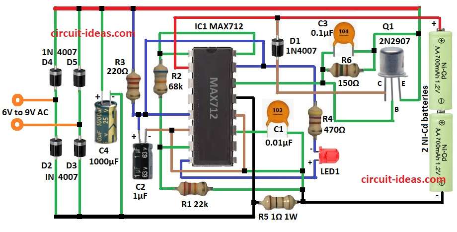
The fast Ni-Cd charger circuit has some main parts working together.
It uses a bridge rectifier, voltage regulator, MAX712 chip and power transistor.
AC input from 6V to 9V comes in and turns into DC which is good for charging Ni-Cd batteries.
First diodes from D2 to D5 a bridge rectifier change AC to DC.
Then capacitor C4 1000µF smooths the DC and removes bumps.
MAX712 IC chip controls charging and checks voltage and current by stops overcharging.
Charging time and working depend on resistor R1 and capacitor C2.
LED1 shows if battery is charging.
Power transistor Q1 controls charging current.
Resistors R5 and R6 help manage current to battery pack.
Formulas with Calculations:
To make our own Ni-Cd fast charger then we can use these formulas:
Charging Current (Icharge):
Icharge = Vout / R
where,
- Vout is the output voltage
- R is the current limiting resistor
Charging Time (Tcharge):
Tcharge = (1.4 × Cbattery) / Icharge
where,
- Tcharge is the time in hours
- Cbattery is the battery capacity in mAh
- Icharge is the charging current in mA
Example:
Battery = 1000mAh and Icharge = 500mA
Tcharge = (1.4 × 1000) / 500 = 2.8 hours
Power Loss in Resistor (P):
P = I² × R
Example:
I = 0.5A, R = 1Ω
P = (0.5)² × 1 = 0.25W
Use a 1W resistor for safety.
How to Build:
To build a Advanced Ni-Cd Battery Fast Charging Circuit following steps need to be followed for connections of the circuit:
- Get all parts shown in the circuit diagram.
- Connect pin 1 of MAX712 IC1 to pin 16.
- Pin 2 goes to positive side of Ni-Cd battery.
- Diode D1 cathode connects to pin 2 and anode to collector of Q1.
- Pin 5 connects to pin 15.
- Resistor R3 connects from positive supply to pin 5.
- Pin 6 connects to pin 12.
- Pin 7 goes between R2 and R1.
- R2 connects from pin 16 to pin 7.
- R1 connects from pin 7 to one side of C1.
- Pin 8 connects to pin 15 through LED1 and resistor R4.
- Pin 11 connects to C1 and R2.
- Pin 13 goes to GND.
- Pin 14 goes to base of Q1.
- Q1 collector goes to pin 2 via D1 and emitter goes to positive supply.
- Connect C3 and R6 in parallel between pin 14 and positive supply.
- Battery positive connects to pin 2 and negative connects to pin 6.
- R5 goes from negative of battery to GND.
- C2 positive connects to pin 15 and negative to other side of R1.
- C4 positive goes to positive supply and negative to GND.
- Diodes D2 to D5 make bridge rectifier and their positive sides to positive supply and negative sides to negtaive supply.
- Connect 6V to 9V AC to bridge rectifier input.
Conclusion:
This Advanced Ni-Cd Battery Fast Charging Circuit charges batteries fast and safe.
There is no long wait as the battery lasts longer.
We can change charge speed and time for different battery sizes.
It is great for hobby people, DIY lovers and for backup power needs.
Leave a Reply