This Automatic Lead Acid Battery Charger Circuit show how to make smart charger for car lead acid battery!
With this charger no need to worry about overcharge.
It will stop charging by itself when battery is full.
It is good for things using car battery like UPS backup power.
Circuit Working:
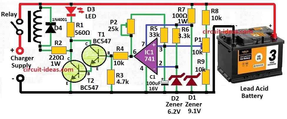
Parts List:
| Category | Item | Quantity |
|---|---|---|
| Resistors (All resistors are 1/4 watt unless specified) | ||
| 560Ω | 1 | |
| 220Ω | 1 | |
| 4.7k | 1 | |
| 33k | 1 | |
| 3.3k | 1 | |
| 100Ω (1W) | 1 | |
| 10k | 3 | |
| Preset 25k | 1 | |
| Preset 10k | 1 | |
| Capacitors | ||
| Electrolytic 100µF 16V | 1 | |
| Semiconductors | ||
| Transistor BC547 | 2 | |
| IC 741 | 1 | |
| Diode 1N4001 | 1 | |
| Zener diode 6.2V | 1 | |
| Zener diode 9.1V | 1 | |
| LED 5mm 20mA | 1 | |
| Relay | 1 | |
| Lead acid battery | 1 |
This circuit is cheap option for costly automatic battery charger for lead acid battery.
We can buy low cost charger and add auto cut-off circuit like this one to save money.
Main part of this automatic charger is comparator.
It compare battery voltage with fixed voltage means reference.
When battery voltage goes high to max level then circuit stop charging by switching relay OFF.
When battery voltage goes low to min level then relay switches ON again and charging continues.
Voltage on non-inverting input goes up with battery voltage.
When non-inverting voltage become more than inverting voltage then after crossing certain level set by P1 comparator switches the relay.
Comparator have hysteresis and is adjusted by P2.
This stop relay from ON and OFF again and again due to small battery voltage change.
It also help to decide when charging should start again for low voltage point.
How to Adjust the Circuit:
Best way is to use variable power supply instead of real battery.
Set power supply to 14.5V and adjust P1 until relay turn OFF and charging stops.
Then change power supply to 12.4V and adjust P2 until relay turn ON again and charging start.
We may need to repeat this many time, because P1 and P2 change each others effect.
Formula:
When making automatic lead acid battery charger using IC 741 op-amp we must build circuit that always check battery voltage and control charging current.
Some formulas and things are important to remember when designing this type of charger:
Voltage Control and Regulation:
Zener Diode for Reference Voltage:
Use zener diode to make fixed voltage called Vref.
Usually Zener value is 6.2V or 9.1V.
So,
Vref = VZ
IC 741 compare battery voltage (Vbat) with Vref then Vref come from voltage divider.
Lets say:
IC 741 get power from Vcc.
Vref is the fixed voltage we use for comparing.
To find resistor values for feedback divider R1 and R2 we use this formula:
Voltage Divider Formula:
Vout = Vcc × [R2 / (R1 + R2)]
In this charger circuit:
R1 = P1 + R8
R2 = R9
So formula becomes:
Vout = Vcc × [R9 / (P1 + R8 + R9)]
This formula help to find correct resistor values for voltage divider in IC 741 charger circuit.
Change resistor values are based on what battery need and what power source we use and how op-amp works.
How to Build:
Below are the connections steps for Automatic Lead Acid Battery Charger Circuit:
Get Comparator Circuit Ready:
- As shown in datasheet connect comparator IC.
- It have one output and two input and one inverting and one non-inverting.
- Make voltage divider with resistors to give fixed voltage to one input.
- Connect battery that we want to charge to other input.
Add Hysteresis:
- To make hysteresis connect feedback resistor from output of comparator to one input.
- This help stop ON/OFF fast switching.
- Use preset P2 to set hysteresis level.
Connect Relay Circuit:
- Connect comparator output to base of NPN transistor.
- Emitter goes to ground and collector goes to relay coil.
- Wire relay so when it turns ON it stop charging.
Protection and Power:
- Use voltage regulator to give stable voltage to circuit.
- Add diode to stop reverse current and protect parts.
Adjustment:
- Use method explain before.
- Use variable voltage power supply which is not real battery.
- Change P1 until relay turn OFF at max voltage.
- Then change P2 until relay turn ON again at low voltage.
- Repeat if needed to get right setting.
- After wiring is don, test with real battery.
- Check relay stop charging when battery is full and start again when voltage drop.
Finish:
- If circuit work good and solder all parts to PCB or keep on breadboard.
- Be careful with all electric parts and connect everything correct to avoid damage.
Conclusion:
This Automatic Lead Acid Battery Charger Circuit checks battery voltage always and change charging current and voltage as needed.
It can do bulk charging, absorption and float charging and these give good performance and long battery life.
This automatic charger is simple, useful and good for keeping lead acid battery healthy.