Audio amplifier is very important in electronics systems.
It make sound signal strong to drive speaker.
TDA2613 is Hi-Fi audio amplifier chip which give good sound and need few extra parts.
This article for Efficient 6 Watt Audio Amplifier Circuit with IC TDA2613 show how to make simple 6 watt amplifier using TDA2613.
The circuit is good for small audio system with low distortion, wide frequency and easy to build.
Circuit Working:
Parts List:
| Component | Specification | Quantity |
|---|---|---|
| Resistors | 1/4 watt 8.2Ω | 1 |
| Capacitors | Ceramic 22nF, 100nF | 1 each |
| Electrolytic 100μF 25V, 220μF 25V | 1 each | |
| Electrolytic 680μF 25V | 2 | |
| Semiconductors | IC TDA2613 | 1 |
| 8Ω Speaker | 1 |
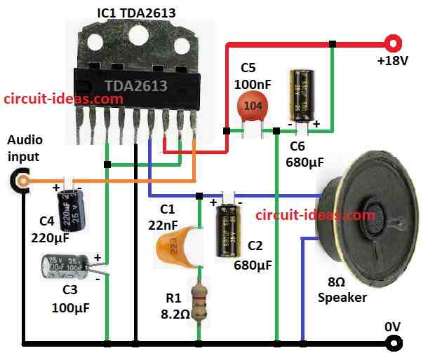
6 watt amplifier circuit using TDA2613 is shown above.
Main part is TDA2613 chip with few passive parts for coupling, decoupling and feedback.
Audio signal goes in pin 9 through capacitor C4 and this capacitor block DC and let only AC audio pass.
IC Chip boost signal and gives output at pin 6.
For stable gain and better sound the feedback parts R1 and C1 are used.
Before going to 8Ω speaker the signal passes capacitor C2, it block DC and send only AC to speaker.
C5 and C6 filters power, reduces noise and ripple by keeping chip work stable.
TDA2613 works on 12V to 24V DC and its best is near 18V like in our circuit.
Power supply must be clean and stable.
Bad supply can make noise and reduce sound quality.
Formulas with Calculations:
Formula for 6W audio amplifier with TDA2613:
Output Power:
P = (V²) / (2 × R_load)
If supply voltage (Vs) is 18V and speaker is 8Ω:
Peak voltage = 18 × 0.7 = 12.6V which is about 70% of Vs
RMS = 12.6 / √2 = 8.91V
P = (8.91²) / (2 × 8) = 4.96W = 5W
In ideal case the chip can give up to 6W.
Coupling Capacitor C2:
C2 helps pass low sound like bass without loss.
Cutoff freq (f_c) = 1 / (2π × R × C)
Set f_c = 20Hz for good bass:
C2 = 1 / (2π × 8 × 20) = 995µF
But 680µF is used here
Still okay which cutoff a bit above 20Hz.
How to Build:
To build a Efficient 6 Watt Audio Amplifier Circuit with IC TDA2613 follow the below steps for connections:
- Take all parts as shown in circuit diagram.
- Connect pin 3 of TDA2613 to GND using capacitor C3 and also connect pin 3 to pin 8.
- Connect pin 5 to GND.
- Connect pin 6 to one side of 8Ω speaker through capacitor C2 and other side of speaker to GND.
- From pin 6 and also connect capacitor C1 and resistor R1 to GND.
- Pin 7 goes to +18V DC and from power line connect capacitor C5 and C8 to GND.
- Pin 9 connect to audio input using capacitor C4 and other side of audio input goes to GND.
Conclusion:
This Efficient 6 Watt Audio Amplifier Circuit with IC TDA2613 is simple and good for small audio work.
It uses less parts, easy to build and sound quality is very good.
If we choose parts right and follow the circuit diagram we can make strong and clear amplifier for better sound.
Leave a Reply