Audio amplifier make weak sound strong and is good for speakers.
This 15W Class B Audio Amplifier Circuit give clear, loud sound and is good for home or DIY.
It uses LM833 op-amp with NPN and PNP transistors for strong boost.
Smart design cut distortion, works well and is efficient for many sound needs.
Circuit Working:
Parts List:
| Component | Specification | Quantity |
|---|---|---|
| Resistors | 10k 1/4 watt | 1 |
| 1M 1/4 watt | 1 | |
| Potentiometer 22k | 1 | |
| Capacitors | Ceramic 0.22µF | 2 |
| Electrolytic 47µF, 25V | 1 | |
| Semiconductors | IC LM833 | 1 |
| TIP41 NPN | 1 | |
| TIP42 PNP | 1 | |
| Diode 1N4148 | 1 | |
| Speaker 8Ω | 1 |
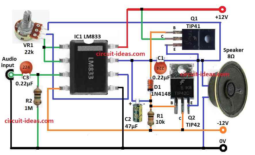
In this circuit audio input goes through capacitor C3 AC coupling.
C3 send signal to pin 3 which is the non-inverting pin of LM833 IC.
C3 block DC and only let AC audio signal pass.
Resistor R3 1M give ground reference for input signal.
LM833 IC first amplify signal.
Gain depends on feedback parts in circuit.
Output from pin 7 goes to base of NPN transistor Q1 TIP41.
Q1 NPN and Q2 TIP42 PNP work in push-pull pair to boost signal.
This setup reduce crossover distortion in Class B amplifier.
Diode D1 1N4148 help smooth switching between Q1 and Q2.
Capacitor C1 help stability and with filter noise.
Capacitor C2 block DC from going to speaker which is the the load.
Circuit uses dual power supply which is +12V and -12V.
Output signal goes to 8 ohm speaker with max power of 15W.
Formulas with Calculations:
Use these formulas to make simple 15W Class B amplifier:
Power Output (P):
P = (V_peak²) / (2 × R)
where,
- V_peak is the peak voltage
- R is the speaker for 8 ohm
Example:
P = (15.5²) / (2 × 8)
P = 240.25 / 16 = 15W
Voltage Gain (A):
A = V_out / V_in
where,
- V_out is the output voltage
- V_in is the input voltage
How to Build:
To build a Simple 15W Class B Audio Amplifier Circuit follow the below mentioned connections steps:
- Put all parts as shown in circuit diagram.
- Connect pin 1 of LM833 IC1 to pin 2 and then to 3rd leg of VR1 pot.
- Pin 3 of IC1 goes to audio input using C3 capacitor and also connect pin 3 to GND using R3 resistor.
- Pin 4 of IC1 goes to -12V.
- Pin 5 goes to GND.
- Pin 6 connect to middle leg of VR1 pot.
- Pin 7 of IC1 goes to one side of 8Ω speaker using C1 capacitor.
- Pin 8 goes to +12V supply.
- First leg of VR1 pot connect to pin 7 and speaker and other end of speaker goes to GND.
- Capacitor C2 connect from pin 7 to base of Q2 transistor.
- Base of Q1 connect to -12V using D1 diode and R1 resistor in series.
- Collector of Q1 goes to +12V.
- Emitter of Q1 connect to emitter of Q2.
- Base of Q2 get signal from pin 7 of IC1 using C2.
- Collector of Q2 goes to -12V.
- Emitter of Q2 connect to emitter of Q1.
Conclusion:
This 15W Class B Audio Amplifier Circuit is easy to make and is good for small audio jobs.
It uses LM833 IC with matching transistors and give good sound with low power use.
If built right then the sound is clear with less distortion.
This circuit is great for hobby and audio lovers.
Leave a Reply