Simple 60 Second Timer Circuit using IC 555 controls timing in many electronic applications, also this circuit uses the 555 timer IC, a popular chip that engineers and hobbyists widely use for timing functions.
Press push button and LED turns ON for about 1 minute.
Also, this circuit is good for delay lights, fun projects or learning electronics.
Circuit Working:
Parts List:
| Components | Values | Quantity |
|---|---|---|
| Resistors | 10Ω 1/4 watt | 1 |
| 10k 1/4 watt | 1 | |
| Preset 1M | 1 | |
| Capacitors | Electrolytic 1000μF | 1 |
| Timer IC 555 | 1 | |
| Tactile Push-Button Switch | 1 | |
| LED any 5mm 20mA | 1 | |
| Power Supply 9V Battery | 1 |
Simple 60 Second Timer uses push button, capacitor, resistors, VR1, LED and 555 timer in monostable mode.
In monostable mode:
Pin 3 output goes LOW until pin 2 get pulse and after trigger pin 3 is HIGH for set time and then gets back LOW.
Steps:
Start with pin 3 LOW then press button and pin 2 get LOW pulse and timer starts.
After that, pin 3 goes HIGH and turns ON the LED and meanwhile, VR1, R2 and C1 set the timing interval.
After time pin 3 goes LOW and LED goes OFF, so adjust VR1 to change time and for 1 minute delay VR1 = 55kΩ.
Formulas and Calculations:
Timer Time (T):
T = 1.1 × R_total × C
where:
- R_total is R2 + VR1
- C is 1000μF
For 60 sec timer:
R_total = 55kΩ
T = 1.1 × 55000 × 0.001
T = 60.05 sec = 1 min
So set VR1 to 55kΩ to get 1 minute timer.
How to Build:
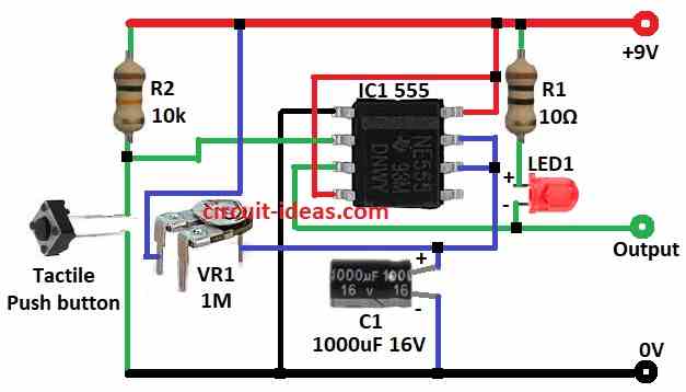
To build a Simple 60 Second Timer Circuit using IC 555 follow below steps for connections:
- First, take all parts as shown in diagram.
- Next, pin 1 of 555 IC connects to GND.
- Now pin 2 connects to push button and other side of button to GND and then R2 connects between pin 2 and +9V.
- After that, pin 3 connects to LED1 and R1 and then to +9V which is the output.
- Then pins 4 and pin 8 connects to +9V.
- Further, pins 6 and pin 7 connect to one side of VR1 and other side of VR1 to +9V.
- Finally, C1 positive connects to pins 6 and pin 7 and C1 negative connects to GND.
Conclusion:
To conclude, this Simple 60 Second Timer Circuit using IC 555 shows how to make time delay; so change VR1 or C1 to set different time.
Also, it is good for beginners to learn basic circuit and timer use and it is an easy design and works well which is useful for small projects.
Leave a Reply