Think about small switches, they only do “ON” or “OFF”, but this Simple Flip Flop Circuit is same like that but for electronics.
It stay in two state like 0 or 1, this small switch is very important it can remember stuff, keep data and help control what happen next like timing and by coordinating things.
Also, we can see these tiny switch everywhere like in computer, in phone and in many electronic things.
Circuit Working:
Parts List:
| Components | Values | Quantity |
|---|---|---|
| Resistors | 1k 1/4 watt | 1 |
| 10k 1/4 watt | 1 | |
| 100k 1/4 watt | 1 | |
| Capacitors | Electrolytic 100µF 25V | 1 |
| Semiconductors | IC 4017 | 1 |
| Transistor BC547 | 1 | |
| Diode 1N4007 | 1 | |
| LED Red 5mm 20mA | 1 | |
| Relay 12V | 1 | |
| Push button | 1 |
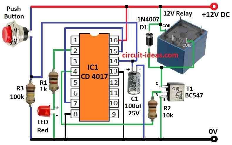
To begin with, this flip flop circuit uses CD4017 IC which is a Johnson counter.
When you press the push button, it sends a pulse to pin 14 (the clock input), pin 2 and 4 go high one after the other in sequence.
Finally, the reset pin connects to ground through the correct output pin so the circuit continues operating properly.
If reset pin connect to any output pin then IC stop counting and output stay high with no change on button press; also this flip flop is good for relay driver circuits.
In this circuit, the CD4017 works like a flip-flop, the inhibit pin, which acts as a clock-stop control, connects to ground so that the IC operates freely without interruption.
Reset pin connect to output pin 7 and so IC only switches between pin 2 and pin 4.
When we press the first button, pin 2 goes high and the red LED turns ON to indicate OFF mode.
Next, when we press the second button, pin 4 goes high and transistor T1 turns ON, switching the circuit to ON mode.
When T1 is ON then relay also turns ON and this keep pressing button to toggle relay ON and OFF.
Formulas:
We can make simple flip flop circuit using push button and parts from circuit mentioned in the above circuit diagram, as it uses IC 4017 which is a decade counter IC.
Use push button to give clock pulse to IC and with each press the output change one time ON next time OFF which works like flip flop.
How to find transistor base resistor:
To stop too much current going to transistor base BC547 uses this formula:
Rbase = (Vout − VBE) / Ibase
where:
- Vout is 12V from IC output
- VBE is 0.7V voltage drop at base emitter
- Ibase is around 10mA with good value for switching
How to Build:
To build a Simple Flip Flop Circuit we need to follow the connection steps mentioned below:
- First, connect Vcc to battery or power supply positive and ground to negative side.
- Next, connect pin 15 of IC 4017 to pin 7.
- After that, connect pin 16 straight to positive power.
- Then connect pin 2 through LED and 1k resistor R1 to ground.
- Connect transistor T1 to right output pin of IC 4017 and also to relay so that current flows correct.
- Connect relay to power and the load like bulb or motor
- Connect push button and 100k resistor R3 to pin 14 of (clock pin).
- Lastly, connect capacitor C1 100µF to the positive leg of pin 14 and negative leg to ground.
Conclusion:
Overall, Simple Flip Flop Circuit used in digital circuit is to keep binary data to help move data at right time and control what happen first or next.
Also, this circuit play a very important parts in computer, microcontroller and other digital system.
Leave a Reply