FM Radio Circuit is an electric brain for the machine and it is also a small electric system which catches FM radio waves and changes to sound we can hear.
This circuit also uses components such as an antenna, microphone, speaker and connecting wires, which are commonly used in many radios to receive music or voice signals.
Below are few type of radios with their qualities:
Radio:
- Radio is an electric device which makes sound using radio waves.
- A radio uses an antenna to receive signals and select the required signal while rejecting unwanted ones, it then amplifies the selected signal and converts it back into voice or music.
- FM radio is very common way to send sound by waves, many other tools also use FM like hospital machines, radar, walkie talkie.
- FM waves are better than AM waves because it is with less noise and problem also on radio FM work between 88 to 108 MHz.
- Also, FM give better sound than AM and catches FM stations and play good sound.
AM vs FM:
- FM send more sound types than AM.
- AM send around 15 kHz and FM send around 4.5 kHz.
- FM radio sound is more clear and nice while FM has bigger range for sound.
Circuit Working:
Parts List:
| Components | Quantity |
|---|---|
| Resistors (All resistors are 1/4 watt) | |
| 10k | 2 |
| 1k | 1 |
| 10Ω | 1 |
| Potentiometer 10k | 1 |
| Capacitors | |
| Ceramic 220nF | 1 |
| Ceramic 2.2nF | 1 |
| Ceramic 100nF | 1 |
| Ceramic 0.047μF | 1 |
| Electrolytic 100μF 25V | 1 |
| Electrolytic 1000μF 25V | 1 |
| Electrolytic 10μF 25V | 2 |
| Trimmer 22pF | 1 |
| Semiconductors | |
| Transistors BF495 | 2 |
| IC LM386 | 1 |
| Coil 4 turn 22 SWG 4mm diameter air core | 1 |
| Speaker 8Ω | 1 |
| Antenna | 1 |
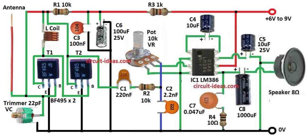
To begin with, this is FM radio circuit uses few parts to catch local FM stations.
Main parts are transistor BF495 T2, 10k resistor R1, coil L, small variable capacitor VC 22pF and transistor BF495 T1; all these parts make Colpitts oscillator.
Furthermore, trimmer VC helps to set the station between 88 to 108 MHz and trimmer 22pF is good because we can easily change its value from few pF to 20pF.
Also, capacitor C1 220nF take sound signal from resistor R1 and send it to sound amplifier and capacitors C3 100nF, C6 100µF 25V and resistor R3 1k makes band pass filter.
The coil L is a small air-core coil, 4 mm wide, made with 4 turns of 22 SWG copper wire also it removes high-frequency signals and allows only low-frequency audio signals to pass.
Moreover, the LM386 provides audio power amplification and produces 1 to 2 watts of output power, which is suitable for a small speaker, here, pin 5 of the IC provides the audio output.
A 22k VR connected to pin 3 controls the volume level.
Circuit works with 6V to 9V battery and how good radio works depends on coil L, antenna type and how far FM station is.
Formulas:
This formula show how LM386 amplifier make signal louder (gain), as it discuses about what happen when we add or do not add capacitor between pin 1 and pin 8.
Formula (No Capacitor):
Gv = 2 × 15K / (150 + 1350)
- Gv mean voltage gain for how much amplifier increase the input sound signal.
- 15k is inside resistance of IC.
- 150 and 1350 are resistance impedance between pin 1 and pin 5/8.
Without a capacitor, the gain remains around 20 times.
In decibels: Gain (dB) = 20 × log(Gv) = 26 dB
With Capacitor:
New formula:
Gv = 2 × 15K / 150
We now place a capacitor between pins 1 and 8 and the capacitor creates a low-resistance shortcut, which removes the 1350-ohm resistance.
Total resistance becomes smaller with 150 ohm only and this make gain go up to 200 times.
In decibels: Gain = 46 dB
Important to Know:
Adding capacitor between pin 1 and 8 makes gain much higher, it is also good for weak sound and makes it louder.
Therefore, high gain can also bring more noise and distortion and for correct capacitor value check LM386 datasheet; it tell what value gives what gain.
How to Build:
To build a FM Radio Circuit follow the below mentioned steps for connections:
Colpitts Oscillator:
- First, connect coil L, 10k resistor R1 and 22pF variable capacitor VC to transistor BF495 T1.
- Next, make coil L with 4 turns of 22 SWG enameled copper wire and the coil should be 4 mm inside.
- After that, use 22pF trimmer as VC which will helps to tune station between 88 to 108 MHz.
- Also, turn the trimmer slowly to catch correct radio station.
Modulation and Signal:
- Now, use capacitor C1 220nF to take signal from resistor R1 and send it to audio amplifier.
- Then connect pin 3 of IC LM386 to a 22k potentiometer VR to control volume and pin 5 of IC LM386 gives louder sound output.
Band Pass Filter:
- Next, use capacitor C3 100nF, C6 100µF 25V and resistor R3 1k to make band pass filter, as this filter remove high frequency and keep low sound frequency and it helps with sound to come clear.
Connect Antenna:
- After that, connect antenna to the circuit and we can use 60 cm copper wire or a telescopic antenna.
- Also, try different wire length to see what gives better signal.
Testing Circuit:
- After building the circuit turn ON the battery and turn the VC trimmer slowly to tune FM station between 88 to 108 MHz; also use VR (volume control) to check sound volume.
Important Notes:
- First, check all soldering and wire connections are correct and if circuit is not working well try small changes or use other parts.
- Do not use too high voltage or it may break the parts as this small FM radio circuit is good for learning and for local FM stations.
Conclusion:
Overall, in this FM Radio Circuit the modern FM radios use ICs that do many jobs in one chip.
Moreover, some circuits also use AFC (automatic frequency control) to keep signal stable when station is weak or there is noise.
Leave a Reply