This article for Induction Heater Circuit teaches us how to make one circuit and this circuit make iron things hot using magnet.
Also, we call this thing “induction heating.”
WARNING: Making this circuit with big current and voltage is dangerous, so so only with adult watching and use good safety gear.
Moreover, it is not good project for new people in eletronics.
What is a Induction Heater Circuit:
Induction heater circuit is electric device which makes heat in one area using rule of electromagnetic induction.
As a result, when we give high frequency magnetic field to metal it makes eddy current inside and this eddy current make metal hot very fast.
People also use induction heater for making metal hard, for science test and for cooking machine.
Circuit Working:

Parts List:
| Components | Values | Quantity |
|---|---|---|
| Resistors | 220Ω 1/4 W CFR | 2 |
| Capacitors | PPC 330nF | 2 |
| Semiconductors | MOSFET IRF540 | 2 |
| Schottky Diode UF4007 | 2 | |
| Coils As specified in diagram above | 3 |
How Induction Heater Work:
In the above circuit diagram, induction heater uses high frequency magnetic field to make eddy current inside iron or metal with magnet power.
Also, this eddy current makes heat and stop free movement of electrons in metal.
For iron heat make is same like current square (I²) times metal resistance (R).
Here, iron resistance is 97 nano ohm mete, so for fast switching this design is very good, also ferrite material used instead of normal iron transformer.
Formula:
Formula Show How Heat Happen in Iron:
This formula tell how resistance, current and heat work together in iron, which show joules law a very important rule in electric.
Heat = I² × R (for Iron)
where:
- Heat is how much thermal energy come in joules (J) or calories (cal).
- I² mean current flow in ampere square.
- R is resistance of heating part in iron or in ohms Ω.
How It Work:
When we plug in and turn ON the iron, current flows into the heating element and this element uses a material with high resistance, which resists the current and produces heat.
Furthermore, this heat come because of that fight between electric and resistance.
Zero Voltage Switching ZVS Technology:
This type of induction heater uses ZVS tech to turn ON MOSFETs electric switches, also ZVS make less heat on parts so system work better.
Here, the circuit can auto match its frequency with capacitor and coil like tank circuit.
Using Oscillator:
It uses Royer oscillator whish is easy and self resonant type; MOSFETs turn ON one after another because all parts have small differences.
Why ZVS is Good:
ZVS (zero voltage switching) turn ON MOSFETs when no big current goes through them and this is safe and cool.
Hence, because of that the circuit can work with heavy load which is up to 1 kVA with no big heatsink needed.
Formula for inductance L1 and capacitance C1 help find resonant frequency of the circuit.
Formula:
Formulas for Induction Heater Circuit:
f = 1 / (2π × √L × C)
where:
- f is resonant frequency of circuit in hertz Hz.
- π (pi) is math number which is about 3.14159, multiply by 2 to get 2π.
- L inductor value measured in henries H.
- C capacitor value measured in farads F.
- √ means square root.
How This Formula Work:
Think like swing.
C capacitor is like person weight on swing and L inductor is like swing chain length.
When we change L or C the swing move faster or slower and the same way we can change frequency in circuit.
Also, this formula say the frequency is opposite to square root of L times C.
Parts Needed Component Specification:
Use MOSFETs like IRF540 for the induction heater because they provide a 110V and 33A rating and heatsinks keep the heat under control.
We can also use other N-channel MOSFETs if they have good enough rating.
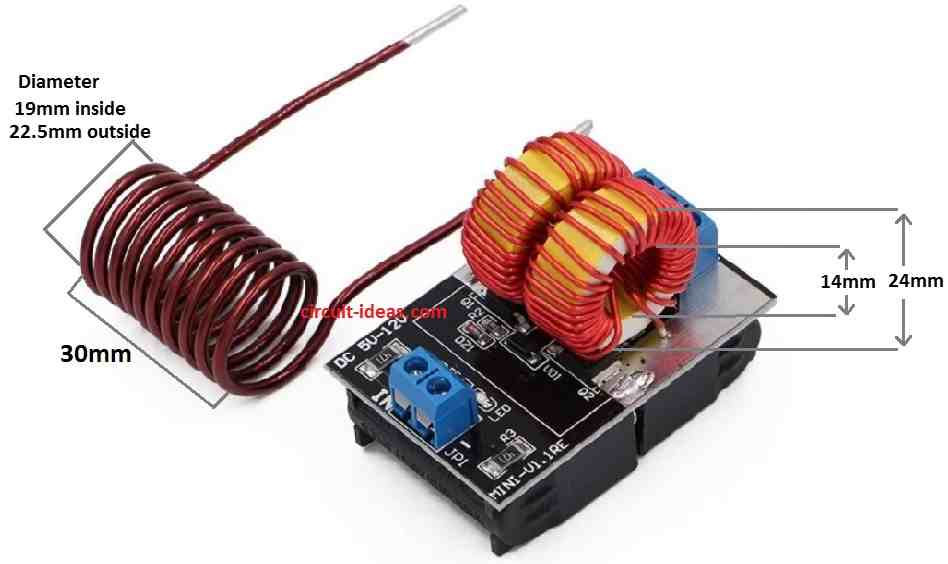
Inductor and Tank Circuit:
Inductor (big coil) work like blocker which stops high frequency from going to power supply, it also keep current in safe limit.
Use thick wire for inductor because current is big and value of this inductor should be more than work coil like 2mH.
Tank circuit has C1 and L1 which makes high frequency and handle lot of heat and current.
Strong Induction Heater Design:
This design uses ZVS method and is based on Mazzilli driver idea which has 2 current limiter coils and 1 work coil.
No center tap needed, because it heat big metal parts fast with push-pull action and both side working together.
Power Output:
If we give 48V and 25A then circuit gives around 1200 watts power, this is very strong it can melt 1 cm thick bolt in less than 1 minute.
Hence, this design module is also easy to find and use.
How to Build:
To build a Induction Heater Circuit following are the steps one should follow:
Make Inductor Ready:
- First, use thick wire with high gauge, wind coil with center tap and inductor value should be around 2mH.
Build Tank Circuit:
- After that, take metalized PP capacitor like 330nF 400V and connect it parallel with inductor L1.
Make Oscillator:
- Then use resistors and capacitors to set Royer oscillator and check values are right so circuit work stable.
Connect MOSFETs:
- After that, use N-channel MOSFETs like IRF540 and connect them correct in circuit; also double check wire and place are OK.
Add Schottky Diodes:
- Also, put Schottky diodes across each MOSFETs gate and source, as this help remove gate charge when not working which is good for fast switching.
Use Quick Recovery Diodes:
- Add fast switching diodes if needed, as these help control current in high frequency.
Check All Connections:
- Look for every wire again and check no loose wire no missing part.
Connect Power Supply:
- Lastly, connect the power supply to circuit and check voltage and current are right for the setup.
Test the Circuit:
- Turn ON the circuit and watch how it works.
- See if it oscillate are correct at resonance frequency.
- Touch parts carefully with no overheating.
Modify If Needed:
- If something does not work good then change some part values and try make it better.
Connect the Load:
- Connect the work coil or metal object to test heating and be careful and follow safety rules.
Conclusion:
To conclude, to make this Induction Heater Circuit we need some electronic skill and wiring knowledge.
Also, if anyone is not sure better to look circuit diagram or ask expert person to help; and always turn OFF circuit when changing anything.