This Long Range Infrared (IR) Remote Control Circuit using TSOP1736 IC show how to make circuit to control fan, TV, light with any remote control.
We can use old remote from home also.
It is fun DIY project which make electronics hobby more easy.
What is a Infrared IR Remote Control Circuit:
Infrared remote control circuit is electronic circuit it help device and remote talk using infrared signal.
We use this kind of remote for TV, DVD player, music system and other electric things.
Circuit have two main parts one is infrared sender in remote and other is infrared receiver in device.
Through this circuit in this post now we can see how this new technology will work and how it will look inside.
Circuit Working:
Parts List:
| Category | Component | Quantity |
|---|---|---|
| Resistors | 1k 1/4W CFR | 8 |
| Capacitors | ||
| PPC 0.01µF | 2 | |
| Electrolytic 1000µF 16V | 1 | |
| Electrolytic 10µF | 2 | |
| Semiconductors | Transistor 2N2222 | 1 |
| IC TSOP1736 | 1 | |
| IC 7805 | 1 | |
| IC 555 | 1 | |
| IC 4027 | 1 | |
| Diode 1N4007 | 1 | |
| LED Red 2mA 5mm | 1 | |
| LEDs Green 2mA 5mm | 3 | |
| Relay 12V | 1 |
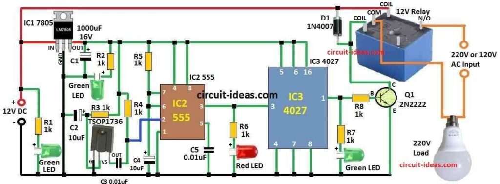
This circuit works with two main ICs IC 4027 decade counter and IC 555 timer.
We can use IR sensor TSOP1736 to catch infrared signal from remote control.
One relay SPDT type is also used.
It work like switch and it can turn power ON or OFF
Circuit need 9V DC battery to work good.
We use 7805 regulator IC to make 9V into 5V and this 5V goes to relay and timer IC and counter IC.
When IR light from remote hit TSOP1736 it make spike signal at 36KHz.
Timer IC 555 take this spike as trigger input.
Then 555 IC give pulse at pin 3 after getting trigger.
We can change parts R5 and C4 to make pulse longer or shorter and this change how long relay stay ON.
This pulse connects to counter IC 4027 and it gives set output from pin 1.
Then transistor Q1 turns ON and it connect relay and relay gives power to load like fan, TV, light.
We can also use R5 and C4 to adjust how long pulse stay which should be at least 1 second.
If IR light keep coming and counter stay in set mode then load keep getting power.
When counter connects to reset mode Q1 stop working and relay will turn OFF and power stops to load.
Formulas and Calculations:
For astable multivibrator circuit to find frequency (f) we need to know values of resistors and capacitor.
Below is how we can calculate:
First we calculate time constant (τ):
τ = (R5 + R4) × C4
τ = (1000Ω + 1000Ω) × 10μF = 20 × 10⁻³ seconds = 20 ms
Now find half-cycle time (thalf):
thalf = 0.693 × τ
thalf = 0.693 × 20 ms = 13.86 ms
Now calculate frequency (f):
f = 1 / (2 × thalf)
f = 1 / (2 × 13.86 ms) = 36.1 Hz
Note:
This frequency value is not always correct it can change because of real part limits or transistor switching delay.
To get exact value better use circuit simulator or advanced math tools.
How to Build:
Follow the below mentioned steps for building a Long Range Infrared (IR) Remote Control Circuit using TSOP1736 IC.
- First collect all parts we need like already told before.
- Choose right transistor type for our circuit and it must work good for our need.
- On PCB put timer IC 555, counter IC 4027, IR sensor TSOP1736, SPDT relay, transistor Q1 and voltage regulator IC 7805.
- Use jumper wires to connect all parts same like in circuit diagram.
- Set timer IC 555 using resistor R5 and capacitor C4 and these will control how long and how often pulse comes.
- Try different R and C values to get good pulse time and duty cycle.
- Connect output of IR sensor TSOP1736 to input pin of timer IC 555.
- Then connect output of timer IC 555 to input of counter IC 4027.
- Wire base of transistor Q1 to output pin of counter IC.
- Relay should connect to transistor Q1s collector and the load like fan or light connect to relay.
- Change resistor and capacitor values to make circuit work and how we want.
- Now test the circuit using IR remote and point it to sensor and check if load turns ON or OFF
- If it works fine we can move parts to protoboard for stronger setup.
- Put whole circuit in a good box if needed and to protect it from dust or damage.
- At end double check all wires and connections are tight and safe.
Advantages of TSOP1736 IC:
- TSOP1736 works for long distance.
- It catches IR signal from far.
- It uses very less power use.
- Gives clean digital output.
- Works even in room light.
- Removes noise from sunlight.
- Small and easy to fix.
- Reliable and stable signal.
- Simple to connect with microcontroller.
- Works with normal TV remote frequency of about 36kHz.
- Its good for home remote projects.
- Gives fast and accurate response.
Note:
- Do not forget to read datasheet of all parts and it tell us pin number and other important things.
Conclusion:
This Long Range Infrared (IR) Remote Control Circuit using TSOP1736 IC uses infrared tech to control home devices like fan, light, TV from far.
If we understand how parts connect and work together we can change pulse time to fit what we need.
This make our small home automation system work good and easy to use.
References:
Wireless Infrared Remote Controller for Multiple Home Appliances
Leave a Reply