To begin with, this smoke alarm circuit works like a house with a sensitive “nose,” because it detects smoke in the air and when it senses smoke, it immediately triggers a loud alarm.
In addition, the alarm can be a buzzer, a blinking light or any other alert device that activates to warn people.
Furthermore, smoke detectors operate in different ways, for example, some use a photoelectric method with a small light beam, while others use an ionization method with a tiny radioactive source.
In both cases, the system detects smoke because smoke disturbs these processes.
The main purpose of this circuit is to improve safety and provide an early warning of a possible fire.
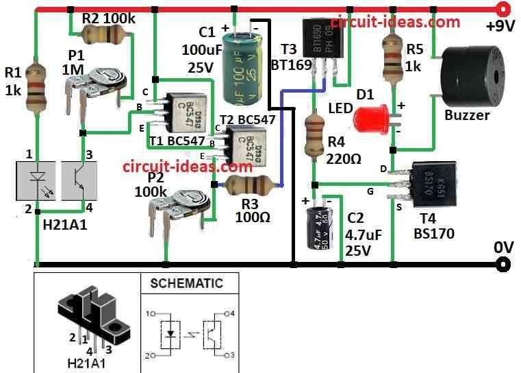
Circuit Working:
Parts List:
| Components | Values | Quantity |
|---|---|---|
| Resistors (All resistors are 1/4 watt unless specified) | 1k | 2 |
| 100k, 100Ω, 220Ω | 1 each | |
| Preset 1M | 2 | |
| Capacitors | Electrolytic 100μF 25V | 2 |
| Electrolytic 4.7μF 25V | 2 | |
| Semiconductors | Transistors BC547 | 2 |
| FET BS170 | 1 | |
| SCR BT169 | 1 | |
| LED Red 5mm 20mA | 1 | |
| Optocoupler H21A1 | 1 | |
| Buzzer | 1 |
This smoke alarm circuit uses a component called the H21A1, it contains a small infrared LED and a phototransistor inside a single package.
Between them, a small gap exists and when smoke enters this gap, it blocks the light beam.
Conversely, when no smoke is present, the light reaches the receiver, and the circuit remains in the OFF state;
But if smoke appears it stop the light and this changes output from ON to OFF.
Then the receiver stop working and two transistors T1 and T2 start working together like one strong switch like Darlington pair and this makes voltage go to another part called SCR which is BT169 T3 and it turn ON.
Moreover, after that power go to one more part that is MOSFET BS170 T4 and then the buzzer start making sound; also, small light that is LED D1 turns ON to show alarm is working.
Finally, the buzzer produces sound continuously until we disconnect it from the 9V battery or turn off the power supply.
Hence, if one wants better working then can adjust trimpots P1and P2 and change resistor R1 a little.
Formulas:
To design a smoke alarm circuit, we need to use basic electronic formulas that help show the correct values of resistors, capacitors, and other components.
Here, are some important formulas we can use:
1. Resistor and Capacitor Values:
Voltage Divider Formula:
Use this to get smaller voltage from big voltage:
Vout = Vin × R2 / (R1 + R2)
where,
- Vin = input voltage
- R1, R2 are the resistor values
- Vout is the output voltage we want
2. Charging and Discharging of Capacitor of Time Delay:
Time constant: τ = R × C
where,
- τ (tau) is how fast capacitor charge or discharge
- R is the resistance in ohms
- C is the capacitance in farads
3. Capacitor Voltage Over Time for RC Charging:
V(t) = Vin × (1 − e^(-t / RC))
where,
- V(t) is the voltage at time t
- Vin is the input voltage
- e is the 2.718 which is the natural log
- t is the time
- R is the resistor
- C is the capacitor
This formula show how voltage builds up in capacitor over time.
4. Transistor Base Current for NPN like BC547:
IB = (Vin − VBE) / RB
where,
- VBE is the base to emitter voltage for around 0.7V for silicon transistor
- RB is the base resistor
- IB is the base current
Hence, with these formulas we can choose parts we already have and test the smoke alarm circuit to be sure it works good.
How to Build:
To build a Smoke Alarm Circuit please follow the below mentioned circuit assembling steps:
- First, examine the circuit diagram carefully and identify how all the components connect.
- Next, ensure that we place the H21A1 module correctly and also, position the LED on one side and the phototransistor on the opposite side of the smoke gap.
- After that, connect H21A1 to other parts same like in diagram.
- Join transistors T1, T2, T3, T4 in Darlington pair way.
- Then connect SCR T3 after Darlington output.
- Now connect MOSFET T4 to gate pin of SCR.
- Change trimpots P1 and P2 and resistor R1 to get better working and these parts help control sensitivity which we can set them based on our needs.
- Give power using 9V DC battery or adapter and now put little smoke in front of sensor slot.
- Lastly, see if LED D1 light up and buzzer makes sound and if it does not work good then adjust again to fix sensitivity.
Conclusion:
To conclude, Smoke alarm circuit is very important safety device as it find smoke in air and turn ON an alarm to tell people there is danger.
Additionally, the system uses a sensor and low-level signals to detect smoke.
When it detects smoke, it immediately triggers a loud alarm and as a result, people can evacuate the area quickly.
Moreover, this early warning helps control fire at an early stage, which can save lives and protect homes.