In this post we will understand about a simple power amplifier circuit using AC176 and AC126 type PNP germanium transistor in OTL (output transformer less) design.
Also, this circuit gives audio power directly to speaker without output transformer, it is low voltage circuit and works with 9V battery.
Therefore, the circuit design is easy and good for small audio projects, this amplifier improves weak audio signal and drives 8 ohm speaker.
Circuit Working:
Parts List:
| Components | Values | Quantity |
|---|---|---|
| Resistors (All resistors are 1/4 watt unless specified) | 68Ω, 1M, 1k | 1 each |
| 1Ω 2watt | 2 | |
| Potentiometer 5k | 1 | |
| Capacitors | Electrolytic 4.7uF 25V, 220uF 25V, 100uF 25V | 1 each |
| Semiconductors | Transistors BC547 NPN, AC176 PNP, AC126 PNP | 1 each |
| Speaker 8Ω | 1 | |
| SPST switch | 1 | |
| Battery 9V | 1 |
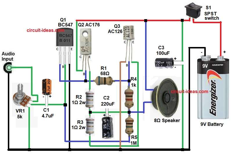
From the above circuit diagram, input audio signal comes from input terminal and VR1 works as volume control which adjusts input signal level.
First, capacitor C1 blocks DC and allows only AC audio signal to pass to base of Q1.
After that, Q1 BC547 works as first stage amplifier which increases small signal voltage, output from Q1 goes to Q3 AC126, Q3 works as driver transistor and it gives more current gain.
Then Q2 AC176 works as output transistor and it handles higher current and drives speaker also this stage gives power amplification.
Furthermore, capacitor C2 connects between driver and output stage and it helps in coupling and stabilizing signal; R1, R2, R3, R4, R5 set biasing for transistors and they keep correct operating point so distortion is low.
Lastly, capacitor C3 acts as a filter capacitor and removes noise from the power supply and the speaker connects directly to the output, so this circuit is an OTL design and does not need a transformer.
Also, switch S1 turns ON and OFF the circuit.
How to Build:
To build a Transformerless Audio Amplifier Circuit using Germanium Transistor following the below connection steps:
- First, gather all the parts as in circuit diagram.
- Next, take Q1 BC547 NPN transistor and connect collector pin to one end of R1 and Q2 base line.
- Then take base pin and connect to C1 positive and negative of C1 connect to VR1 middle pin.
- After that take emitter pin and connect to negative of 9V battery.
- Next, take Q2 AC176 PNP transistor and connect emitter pin to one end of resistor R2.
- Then take base pin and connect to other end of resistor R1 and one end of resistor R4.
- After that take collector pin and connect to positive supply of 9V battery.
- Next, take last Q3 AC126 PNP transistor and connect emitter pin to one end of resistor R3.
- Then take base pin and connect between collector of transistor Q1 and one end of resistor R1.
- Last collector pin connect to negative of 9V battery.
- After that take VR1 pot and connect upper pin to audio input, middle pin to negative of capacitor C1 and lower pin to negative of 9V battery.
- Next, take C2 capacitor and connect positive end between resistor R2 and R3 and negative end connect to one end of resistor R4 and one end of 8Ω speaker.
- Then take capacitor C3 and connect across supply for filtering from positive of 9V battery and negative of battery.
- 8Ω speaker one end connect to positive of 9V battery and other end between the junction of resistor R2, R3 and R4.
- Lastly, connect switch S1 to the positive line of 9V battery.
Conclusion:
To conclude, this Transformerless Audio Amplifier Circuit using Germanium Transistor gives simple and low cost audio amplifier, which uses germanium transistors so sound is warm but components are old type.
Also, design is easy for beginners, so no output transformer needed because circuit size is small and output power is low but enough for small speaker.
Hence, this circuit is good for learning audio amplifier basics.
Leave a Reply