Simple Magnet Polarity Detector Circuit using Hall Effect Sensor is important for things like motor control, measuring magnetic field and for teaching.
Also, this article show how to use APX9141 Hall Effect sensor to make easy and working magnet polarity detector.
Red and blue LEDs show magnet north and south poles and it gives simple visual signal; also circuit uses small 3V CR2032 battery which is is small, easy to build, good for learning and for hobby.
Circuit Working:
Parts List:
| Components | Quantity |
|---|---|
| IC APX9141 Hall Effect Sensor | 1 |
| Red LED 5mm 20mA | 1 |
| Blue LED 5mm 20mA | 1 |
| CR2032 Battery 3V | 1 |
| Tactile Switch | 1 |
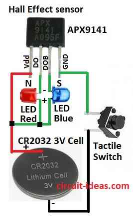
The APX9141 Hall Effect sensor is the main part of this simple circuit, which uses easily available components.
Here, sensor has Hall element and two outputs with DO and DOB to find magnet poles fast and also APX9141 can detect magnetic field and give voltage based on field strength and pole.
In this circuit magnet pole decide which LED turns ON when it is near the sensor.
Red LED pin 2 shows North pole and blue LED shows pin 3 and DOB shows South pole.
Sensor works with 3V so it uses CR2032 battery and user can use small push switch to turn circuit ON/OFF and to save battery.
Formulas:
This circuit uses important formula for LED current:
I = (Vsupply − VLED) / Rinternal
where:
- I is current through LED
- Vsupply is battery voltage from 3V from CR2032
- VLED is LED forward voltage drop
Rinternal is batteries internal resistance
How to Build:
To build a Simple Magnet Polarity Detector Circuit using Hall Effect Sensor follow the below mentioned steps:
- First, connect Vdd pin of APX9141 to positive (+) of CR2032 battery.
- Next, connect anode the long leg of Red LED to positive (+) and cathode the short leg to DO pin of APX9141.
- After that, connect anode of Blue LED to positive (+) and cathode to DOB pin of APX9141.
- Now connect GND pin of APX9141 to negative (–) of battery through tactile switch.
How to Test:
- Press switch to turn ON circuit, then bring magnet close to the sensor.
- After that, red LED lights for north pole and blue LED lights for south pole.
Conclusion:
To conclude, this Simple Magnet Polarity Detector Circuit using Hall Effect Sensor is easy and smart way to check magnet polarity using APX9141 sensor.
Furthermore, we can use it for learning and for small projects and also apply it to many technologies to deeply explore magnets and sensors.
Leave a Reply