IC CD 4093 Based PWM DC Motor Controller Circuit control motor speed and save power.
Change PWM duty cycle to adjust motor speed by changing voltage.
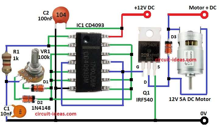
Circuit use CD 4093 NAND Schmitt trigger and MOSFET for smooth running.
Use 12V power supply and 5A for this circuit.
Circuit Working:
Parts List:
| Component | Specification | Quantity |
|---|---|---|
| Resistors | 1k 1/4 watt | 1 |
| Potentiometer 100k | 1 | |
| Capacitors | Ceramic 100nF | 2 |
| Semiconductors | IC CD 4093 | 1 |
| MOSFET IRF540 | 1 | |
| Diodes 1N4148 | 3 | |
| Motor 12V 5A DC Motor | 1 |
First stage is oscillator where IC1 CD 4093 NAND gate work as astable multivibrator and make square wave.
Frequency depend on R1, VR1 (adjustable) and C1.
Second stage is PWM generation, D1, D2 and VR1 control duty cycle.
Changing VR1 changes C1 charge/discharge so duty cycle changes.
Third stage is signal processing where output goes to other NAND gates to buffer and clean signal for MOSFET Q1.
Last stage is motor control where MOSFET Q1 switch motor ON/OFF fast.
Speed is control by PWM duty cycle.
Flyback diode D3 protect circuit from motor voltage spikes.
Formulas:
Formula for oscillator frequency PWM:
f = 1.44 / ((R1 + 2 × VR1) × C1)
where,
- R1 is 1kΩ = 1000Ω
- VR1 is 100kΩ = 100000Ω (variable)
- C1 is 10nF = 10 × 10⁻⁹ F
How to Build:
To build a IC CD 4093 Based PWM DC Motor Controller Circuit follow the below mentioned steps for connections and assembling:
- Assemble parts as per circuit diagram shows:
- Connect IC1 CD 4093 pin 1 to pin 2
- Connect pin 5 to pin 6
- Connect pin 8 to pin 9
- Connect pin 12 to pin 13
- Connect pin 7 to GND
- Connect pin 14 to +12V DC
- Connect pin 3 to inputs of all other gates
- Connect diodes D1 and D2 in parallel from pin 3
- Connect one leg of pot VR1 to D1 cathode and other leg to D2 anode
- Connect center leg of VR1 to one end of resistor R1
- Connect other end of R1 to pin 1 and pin 2
- Connect capacitor C1 between R1 and GND
- Connect capacitor C2 between +12V DC and GND
- Connect MOSFET Q1 gate to pin 10 of IC1
- Connect Q1 drain to D3 anode
- Connect D3 cathode to motor + terminal
- Connect motor parallel to diode D3
- Connect Q1 source to GND
Conclusion:
This IC CD 4093 Based PWM DC Motor Controller Circuit controls DC motor speed with low power loss.
CD 4093 IC makes PWM signal and MOSFET switches motor ON/OFF fast.
Speed changes by turning variable resistor VR1.
It is good for fans, robots and motor control in machines.
Leave a Reply