A Powerful Metal Detector Circuit offers high sensitivity and can detect many types of metals at different depths.
However, the most important part of the circuit is the coil.
Furthermore, a large coil can detect objects buried deeper underground, while a small coil works better for locating smaller items, therefore, using interchangeable coils provides the best performance for a wide range of applications.”
Circuit Working:
Parts List:
| Components | Values | Quantity |
|---|---|---|
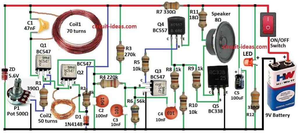
| Resistors (All resistors are 1/4 watt unless specified) | 390Ω, 1.8k, 270k, 220k, 56k, 18Ω | 1 each |
| 330Ω, 1k, 10k | 2 each | |
| Potentiometer 500Ω | 1 | |
| Capacitors | Ceramic 47nF, 100nF | 1 each |
| Ceramic 10nF | 2 | |
| Electrolytic 100µF 25V | 1 | |
| Semiconductors | Transistor BC547 | 3 |
| Transistor BC557, BC338 | 2 each | |
| Zener diode 5.6V | 1 | |
| Diode 1N4148 | 1 | |
| Coil 70 turns (see text), Coil 50 turns (see text) | 1 each | |
| LED any 5mm 20mA | 1 | |
| Speaker 8Ω | 1 | |
| Switch ON/OFF Switch | 1 | |
| Battery 9V | 1 |
To begin with, metal detector find many metal types like ferrous (iron, steel) and non-ferrous (gold, silver, aluminum).
Also, some can tell difference between gold nugget and aluminum ring pull.
But this circuit is simple and works by AM (amplitude modulation), when metal is near coil then magnetic flux changes and makes eddy current.
Eddy current uses flux so coil output goes down.
Second transistor turns OFF a bit and collector voltage goes up and this makes transistors 3 and 4 start oscillate and sending signal to transistor 5 which drives speaker.
Circuit focus on reduced amplitude when metal is near.
First coil and capacitor make tuned circuit and second coil amplifies signal drop.
1mV drop in main oscillator makes 70mV drop in second coil and causes transistor 2 to turn OFF a little and speaker buzz.
Blocks:
Feedback Oscillator like transistor 1, coils from 70 and 50 turns, capacitor 47nF, diode, resistor 1.8k, zener 5.6V stabilize 15kHz frequency.
VCO: transistor 3 and 4 with 10nF capacitor make variable frequency oscillator.
Driver transistor 5 connects oscillator to speaker 8 ohm for clicking sound.
Supply voltage must be stable and Zener diode must helps and then this temperature changes and can cause instability; also this simple circuit is sensitive and has audio output.
Furthermore, metal detectors used in industry for food safety, security, coin machines and more; also try different coil sizes carefully and bigger coil gives deeper detection but needs more power and voltage.
Hence, be careful working with electricity, especially if beginner.
Formulas:
To build strong metal detector first make sensitive oscillator and then it can find changes in electromagnetic field from nearby metal.
Basic formula for frequency (f):
f = 1 / (2π × √(L × C))
where,
- L is coil inductance and C is capacitor value.
Therefore, this gives basic idea to make metal detector circuit but for best result we need more testing and design with right parts and circuit.
How to Build:
To build a powerful metal detector circuit follow the below mentioned steps:
Prepare the PCB:
- If using kit then follow instructions to prepare PCB and if making from scratch then design and etch PCB or use breadboard to test.
Assemble Components:
- First, solder parts on PCB like circuit diagram shows and the put transmitting and receiving coils on PCB as design says.
Connect the Power Source:
- After that, connect the positive and negative terminals of the power source e.g. 9V battery to the PCB as the diagram.
Test the Circuit:
- Now before we close the box test circuit to be sure it works well and use metal object to check detectors sensitivity and range.
Adjust Settings:
- If circuit have adjustable settings like sensitivity or frequency then change them to make it work best.
Calibrate the Detector:
- Adjust detector settings to fit our place and the metals we want to find.
Use and Maintain:
- Use metal detector as its instructions say and check and fix circuit often to keep it working good.
Conclusion:
Overall, to build Powerful Metal Detector Circuit put parts and solder on PCB and then connect power source, test circuit and adjust settings for best work.
Hence, for this circuit we need basic electronics skill but it is a good project for hobby and fun.
Leave a Reply