A 1.5V Audio Amplifier Circuit is small circuit it makes sound signal more strong using only 1.5V battery.
This type of circuit is low power amplifier which is good for things that uses battery or when big power is not there or not needed.
Circuit Working:
Parts List:
| Type | Value | Quantity |
|---|---|---|
| Resistors (All resistors are 1/4 watt unless specified) | 20k | 1 |
| 10k | 1 | |
| 1k | 1 | |
| 1M | 1 | |
| 100k | 1 | |
| Capacitors | Ceramic 1µF | 1 |
| Ceramic 0.01µF | 1 | |
| Semiconductors | Transistor 2N3904 | 1 |
| Transistor 2N3906 | 1 | |
| Transistor 2N2222 | 1 | |
| Speaker 8Ω | 1 |
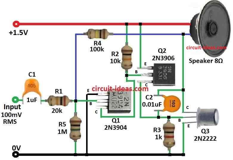
This Class A audio amplifier uses only three transistors and it give 25mW power into 8 ohm speaker or 50mW into 4 ohm speaker by using just 1.5V battery.
Even though power is small the sound still is loud enough for especially with earphones.
But how loud it sound also depend on speaker quality and box design.
Sound range is good because transistors connect directly and it connects from 8Hz to more than 50kHz.
One problem is quiet current (quiescent current) which always go through speaker and so is not good for high power stuff.
Transistors are NPN, PNP, NPN and this setup help push last transistor hard so it works better.
Efficiency is about 20% and almost max possible for Class A to 25%.
Class A always uses same battery power even when there is no sound so battery does not last long.
Not like Class B or AB which save power.
To make sound less distorted need negative feedback which helps clean the signal and reduce gain from 190 to 5.
Gain at each stage is small which is especially at Q2 which is only 1.4 and this is because Q2 push signal to Q3 which has low resistance.
It is hard to make amplifier stable so we needed 0.01uF capacitor between base and collector of Q3 to stop bad behavior.
Still signal at base is not clean because there some distortion were still there and maybe small oscillation happening.
Q3 base can act weird at low voltage like negative resistance which maybe is very useful for making oscillator.
Maybe try germanium or MOSFET transistors.
Germanium work better at low voltage as people say.
But be careful high frequency noise like ultrasound can hurt ears.
Always check AC output before using headphones to stay safe.
Formulas:
This small audio amplifier work with just one 1.5V battery.
It use two transistors first one is common emitter type and second one is emitter follower for output.
Some basic formula for transistor amplifier are below.
The exact result need real transistor information and load details.
Transistor Current Gain (Beta or hfe):
Ic = β × Ib
where:
- Ic is current at collector
- β or hfe is how much transistor can multiply current
- Ib is current at base
Voltage Gain (Av):
Av = -Rc / Re
where:
- Av is how much voltage increase
- Rc is resistor on collector
- Re is resistor on emitter
Power Gain (Ap):
Ap = Av × Ai
where:
- Ap is power gain
- Av is voltage gain
- Ai is current gain
Output Power (Po):
Po = (Vp-p)² / (8 × Rl)
where:
- Po is power that goes to the speaker
- Vp-p is voltage from top to bottom from peak to peak
- Rl is speaker resistance of load
Note:
These formula help to understand how transistor amplifier works.
But for more correct result we need to check with real transistor data or use circuit simulator software.
How to Build:
To build a 1.5V Audio Amplifier Circuit we need to follow the below mentioned connections steps:
Transistor Choice:
- Pick good NPN, PNP and NPN transistors for this amp.
- Be sure they can handle the power and work well in Class A mode.
Circuit Design:
- Use the circuit diagram to build the amplifier.
- Set correct bias and coupling for Class A working.
Parts Selection:
- Choose right resistors and capacitors for the circuit and transistors.
- Use good quality parts for better sound.
Building the Circuit:
- Put the transistors, resistors and capacitors on breadboard or PCB.
- Connect all parts with wire or PCB tracks and check all connections and correct polarity.
Testing the Amp:
- Connect 1.5V battery or power to the circuit.
- Connect a speaker to the output.
- Give small audio input and check if it is working and adjust bias if needed for Class A.
Put in Box:
- Put the amplifier inside a box to protect it and make it look better.
- Be sure air can flow to stop overheating.
Final Test:
- Try the amp with different sound sources and speakers.
- Use oscilloscope or multimeter to check for sound problems like distortion and fix circuit if needed.
Using the Amp:
- Now the amp is ready and we can use it to make small audio louder from phones, MP3 or other devices.
Note:
- Making circuits need basic electronics and soldering skills.
- If anyone is not sure how then ask someone who know or check online videos and tutorials.
Conclusion:
A 1.5V audio amplifier circuit is small and simple way to make sound louder using low voltage.
It is good for things that uses battery where big voltage is not possible or not needed.
With just one transistor and some basic parts this amplifier can make sound strong enough for many uses and also to save power.
Leave a Reply