In our previous article, we made a Simple 1.5V White LED Flasher Circuit using transistors and ferrite coil, but in this article we have design a Simple 1.5V Single Cell LED Flasher Circuit without ferrite coil.
This circuit works only with one 1.5V battery cell, so it is very useful for small battery projects and simple battery operated use.
Moreover, this circuit uses two transistors, few resistors and capacitors for making the LED blink continuously, because the design is very simple, beginners can easily make it and test it on breadboard or PCB.
Also, this circuit is very good for learning transistor switching and capacitor charging working concept.
Circuit Working:
Parts List:
| Components | Values | Quantity |
|---|---|---|
| Resistors (All resistors are 1/4 watt) | 100k, 56Ω | 1 each |
| 820Ω | 2 | |
| Capacitors | Ceramic 0.01uF | 1 |
| Electrolytic 10uF 25V, 100uF 25V | 1 each | |
| Transistor NPN BC547 | 1 | |
| Transistor PNP BC557 | 1 | |
| LED White LED 3mm | 1 | |
| 1.5V AA / Pencil Cell | 1 |
First, when we connect the 1.5V battery cell, resistor R1 gives bias current to transistor Q1 and as a result, Q1 starts conducting.
Next, capacitor C2 starts charging slowly through the connected path and because of this charging action, transistor Q2 receives base drive through resistor R2 and capacitor C1.
Then, Q2 turns ON and current flows through LED and resistor R4, therefore, the LED glows.
After that, capacitor C3 charges and discharges through resistor R3 and this action changes the bias condition of Q2.
Consequently, Q2 turns OFF after a short time and the LED turns OFF.
Again the capacitors recharge and discharge in cycle and hence, the LED continues blinking again and again.
So, in simple words the charging and discharging of capacitors control the ON and OFF switching of the transistors and because of this, the LED flashes.
Formulas with Calculations:
- Basic timing formula:
T = 0.693 × R × C
where:
- T is the time in seconds
- R is the resistance in ohms
- C is the capacitance in farads
Example for calculation using C3 and R3:
R3 = 56 ohm
C3 = 100 uF = 100 × 10^-6 F
T = 0.693 × 56 × 100 × 10^-6
= 0.00388 seconds
This means the time is about 0.00388 second where the circuit works very fast and changes ON/OFF quickly
Now for slower blinking, capacitor C2 plays an important role.
Using R1 and C2:
R1 = 100000 ohm
C2 = 10 uF = 10 × 10^-6 F
T = 0.693 × 100000 × 10 × 10^-6
T = 0.693 seconds
So, the LED blinking interval is around 0.7 second, this means the LED flashes nearly once every second.
2. LED current calculation:
Use Ohms law:
I = V / R
For LED resistor R4:
I = 1.5 / 820
I = 0.00183 A
I = 1.83 mA
So, the LED current is about 1.8 mA which is safe for low power blinking.
How to Build:
To build a Simple 1.5V Single Cell LED Flasher Circuit following steps are required for connections:
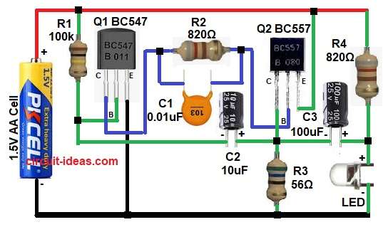
- First, start by gathering all the circuit parts as in diagram above.
- Next, start with Q1 BC547 transistor collector pin connect to one end of resistor R2 and capacitor C1 in parallels.
- Base pin connect to one end of resistor R1 and capacitor C2 negative.
- Emitter connect to battery negative line
- Then start with Q2 BC557 transistor with collector pin connect to the junction of capacitor C2 positive, capacitor C3 negative, and resistor R3 one end.
- Base pin connect to other end of resistor R2 and capacitor C1.
- Emitter pin connect to battery positive line
- Resistor R1 connects from positive supply to Q1 bias point
- R2 connects between Q1 collector pin and Q2 base pin.
- R3 connects between capacitors C2 and C3.
- R4 connect from positive line in series between LED anode and capacitor C3 positive and LED goes to negative line.
- Finally, battery (+)positive terminal connect to positive supply rail and negative terminal goes to (-) negative rail of the battery.
Conclusion:
This Simple 1.5V Single Cell LED Flasher Circuit is simple, low-cost and easy to build project.
The circuit works well with a single battery cell, so it is perfect for small electronic projects and learning purposes.
Also, by changing resistor and capacitor values, we can change the blinking speed easily.
Therefore, this circuit is an excellent beginner project for understanding transistor switching and timing circuits.
Leave a Reply