This 1.5V to 5V Voltage Converter using IC MAX756 works like small power booster for battery, as it takes low 1.5V battery like AA battery and makes it higher like 5V.
Moreover, this help for running small electronic things that need 5V for working good; also the MAX756 chip is like small hero it help circuit change voltage in smart way.
Circuit Working:
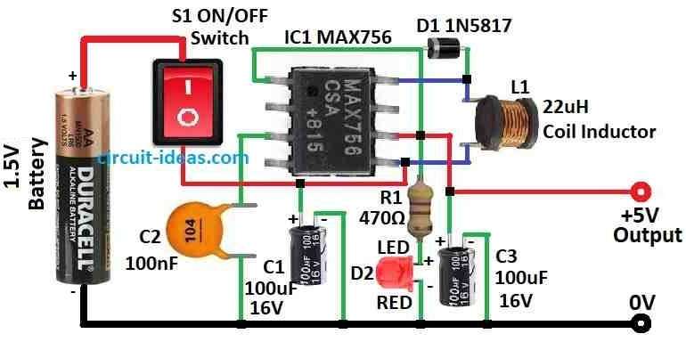
Parts List:
| Components | Values | Quantity |
|---|---|---|
| Resistor | 470Ω 1/4 watt | 1 |
| Capacitors | Ceramic 100nF | 1 |
| Electrolytic 100µF 16V | 2 | |
| Semiconductors | IC MAX756 | 1 |
| Diode 1N5817 | 1 | |
| LEDs Red 5mm 20mA | 1 | |
| Coil Inductor 22uH | 1 | |
| ON/OFF Switch | 1 | |
| Battery 1.5V | 1 |
This circuit gives stable 5V DC power up to 200mA from normal 1.5V AA battery, also the main part in this design is MAX756 chip from Maxim which is a step-up switch chip for low battery power stuff.
The MAX756 can take a small voltage, such as 0.7V and increase it to 5V or 3.3V as needed.
Moreover, this chip works very efficiently and provides more than 87% power efficiency when fully loaded.
Inside the chip it have switch regulator, N channel MOSFET, voltage reference and power fail detector all in one chip.
The sense FET, a special type of MOSFET, provides better efficiency and operates even when the battery voltage drops to 1.1V.
We can make this circuit easy on small PCB and keep wires and connections short and if possible use good 8 pin DIP socket for chip it will help.
Also, power inductor L1 is important its DC resistance should be very low like 0.03 ohm or less for good efficiency.
Capacitors also matter their ESR (equivalent series resistance) affect the efficiency and use low ESR type capacitors for best performance.
Formula:
Before using the formula, we should know that although the MAX756 operates in boost converter circuits, its designers did not primarily intend it for that purpose.
therefore, it may not be the best choice for all cases.
Here is formula:
Vout = Vin / (1 – D / Dmax)
where:
- Vout is the output voltage
- Vin is the input voltage
- D is the duty cycle for how much time switch is ON
- Dmax is the max duty cycle chip can allow
As a result, this formula means output voltage goes up when duty cycle goes up, but IC have a limit and that is Dmax so output voltage cannot go higher than what Dmax allow.
How to Build:
To build a 1.5V to 5V Voltage Converter Circuit using IC MAX756 use the following steps mentioned below:
Make the PCB:
- First, make or get PCB layout for the circuit and then put all parts on PCB same like in circuit diagram.
Solder parts:
- Next, solder IC socket if using and all other parts on PCB and start with small parts first then big ones.
Connect parts:
- Then use thin wire with insulation to join parts like in diagram and keep wires short and neat.
Put the IC:
- If anyone is using socket then put MAX756 chip in socket, but be sure notch on IC should also match with notch on socket.
Test the circuit:
- Put 1.5V AA battery in holder and check LED should turn ON that means circuit is working and giving 5V output.
Finish the circuit:
- If all is working good then fix parts and wires with hot glue or other glue so that they do not move.
Note:
- Be careful while working with electronics and use safety glasses and stay safe from static electricity.
Conclusion:
To conclude, 1.5V to 5V Voltage Converter Circuit using IC MAX756 chip give easy and good way to change low 1.5V to stable 5V.
Furthermore, it is also good for powering many small electronic things using one AA battery or same type power.
Finally, this circuit is not hard to make and it needs only few parts and give reliable 5V with nice efficiency.

Leave a Reply