This project show how to read IR remote signals using Arduino and for that we used TSOP1738 IR sensor.
Arduino can detect button press from remote and also this project for Simple Arduino IR Remote Control Decoder Circuit is simple and easy for beginners.
Arduino Code:
#include <IRremote.h>

int receiver = 2;
IRrecv irrecv(receiver);
decode_results results;

void setup() {
  Serial.begin(9600);
  irrecv.enableIRIn();
}

void loop() {
  if (irrecv.decode(&results)) {
    Serial.println(results.value, HEX);
    irrecv.resume();
  }
}
Coding Explanation:
- We include IRremote library.
- Define pin D2 as input for IR sensor.
- Setup serial monitor 9600.
- Enable IR receiver.
- Loop check IR data.
- Print value in HEX format on serial monitor.
Circuit Working:
Parts List:
| Components | Quantity |
|---|---|
| Resistor 220Ω | 1 |
| Arduino Uno / Nano | 1 |
| IR Receiver (TSOP1838) | 1 |
| Any LED 5mm 20mA | 1 |
Circuit give 5V power to Arduino Uno or Nano and then Arduino is ready to read signals.
TSOP1838 receive IR light from remote and only receive correct frequency of about 38 kHz.
Then the remote sends an IR light signal and the IR receiver detects it and converts it into digital pulses.
The IR receivers output pin connects to the Arduinos digital pin and the Arduino reads the HIGH and LOW pulses.
LED1 acts as an indicator light, and the 220Ω resistor R1 limits the current flowing to the LED.
Now Arduino program decode pulses to find which button pressed and each button have unique code; then Arduino show code on Serial Monitor OR control LEDs / devices.
When we press other button then Arduino detect new code and also the circuit keep running as long power is ON.
How to Build:
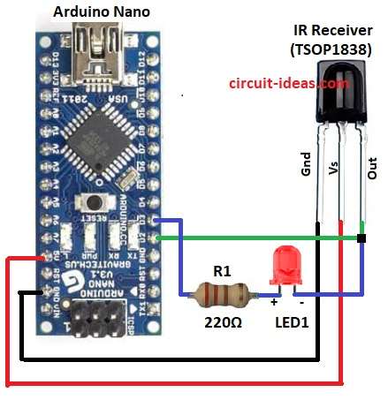
To build a Simple Arduino IR Remote Control Decoder Circuit follow the below mentioned connections:
- First, gather all the parts as shown in circuit diagram
- Next, connect GND pin of IR sensor to GND on Arduino
- Then connect Vs pin of IR sensor to 5V on Arduino
- After that, connect Out pin of IR sensor to D2 pin on Arduino
- Finally, connect LED anode with resistor R1 from Out pin of IR sensor to Arduino D3 pin
Note:
- Use any TV/DVD set-top box remote.
- Point it towards the front of TSOP1838 (the black dome sensor).
- When we press a button remote sends invisible IR light (38kHz pulses).
- TSOP1838 receives it and sends digital signal to Arduino.
- Arduino decodes it and shows the code on Serial Monitor.
- LED on D3 blinks shortly to show signal received.
- Note down the HEX code values shown in Serial Monitor.
- We can later use these specific codes in our program to control motors, relays or other devices.
Conclusion:
To conclude, this Simple Arduino IR Remote Control Decoder Circuit is simple but smart, it can read any button from your TV or remote and make Arduino act.
Furthermore, easy to build, easy to use and fun to learn electronics and also with this our Arduino can see remote signals and control things like magic!
Leave a Reply