This Automatic Night Lamp Circuit using IC 555 works like smart switch for night light.
It have one special light sensor called LDR to check how much light is outside.
When night come and outside become dark the circuit turns ON the lamp by itself.
Then when morning comes and light comes back it turn OFF the lamp again.
It does all this with a small chip called IC 555 working like timer.
Circuit Working:
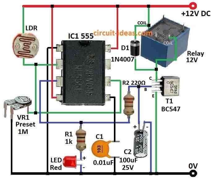
Parts List:
| Category | Component | Quantity |
|---|---|---|
| Resistors | 1k 1/4 watt | 1 |
| 220Ω 1/4 watt | 1 | |
| Potentiometer 1M | 1 | |
| Light Dependent Resistor (LDR) | 1 | |
| Capacitors | Ceramic C1 0.01µF | 1 |
| Electrolytic C2 100µF 25V | 1 | |
| Semiconductors | IC 555 | 1 |
| Transistor BC547 | 1 | |
| Diode 1N4007 | 1 | |
| Red LED 5mm 20mA | 1 | |
| 12V Relay | 1 |
This circuit turn ON light around 6 PM and turn OFF in morning by itself.
It use one light sensor called LDR and the DR can see dark and light.
Not like other LDR circuits but this one is with no flicker.
It works with CFL and tube light also.
It uses IC 555 chip for proper ON/OFF like Schmitt trigger.
Main parts are LDR and IC 555.
LDR change resistance with high in dark to about 10MΩ and low in light to about 100Ω.
This will help circuit to know when it is day or night.
LDR send signal to IC 555 and this IC works like Schmitt trigger using two comparators.
Pin 6 and pin 2 connects to LDR and VR1 preset.
At day time LDR gives more current and voltage at pin 6 goes above 2/3 VCC and IC output become low where light gets OFF.
At night time LDR resistance goes high and voltage drops.
Pin 6 < 2/3 VCC, pin 2 < 1/3 VCC and IC output goes high with pin 3 and turns ON transistor T1.
Relay connected to T1 turns ON and gives power to lamp.
Only live wire goes through relay and neutral stays same.
VR1 adjust how much dark to turn light ON.
Capacitor C2 keep transistor voltage stable and stops relay flicker.
Diode D1 stops back power when transistor is OFF.
Keep LDR away from lamp light and put it where it sees only sunlight.
Use 12V relay and follow circuit diagram for wire connections.
Formulas:
In this circuit one divider is made using LDR and potentiometer like a variable resistor.
This divider give one voltage to IC 555 pin 5 which is the control pin.
If we say Rpot is the resistance of potentiometer then we need to set some value which is called as Rpotadj and other is LDR resistance:
Total resistance (Rtotal) = RLDR + Rpotadj
Voltage at middle poin is the Vjunction where both connect:
Vjunction = VCC × Rpotadj / (Rpotadj + RLDR)
This voltage go to IC 555 pin 5 and help it to decide when to turn ON or OFF
How to Build:
To build a Automatic Night Lamp Circuit using IC 555 we need to follow the below mentioned steps:
- Take LDR and connect it in series with preset VR1
- One end connects to positive power Vcc.
- Join the middle point (junction) of LDR and VR1 to pin 6 (threshold) and pin 2 (trigger) of IC 555.
- Take resistor R2 220Ω and connect it to base of transistor T1 BC547.
- From pin 3 of IC 555 connect a 1k resistor R1 and red LED to ground.
- Connect pin 1 of IC 555 directly to ground.
- Pin 4 (reset) connect to Vcc as this stop the chip from resetting by mistake.
- Pin 5 connect to a small capacitor C1 0.01μF and the other side of capacitor is connected to ground.
- Connect pin 4 and pin 8 both to the positive power Vcc.
- T1 transistor collector connect to one side of relay coil.
- T1 emitter connects straight to the ground.
- Relays common (COM) terminal connects to the phase (live) wire of the lamp.
- Relays NO (normally open) terminal connect to neutral wire of lamp.
- Put diode D1 1N4007 across relay coil and anode negative connects to T1 collector and cathode positive connects to Vcc.
- This protect from back current (back e.m.f.).
- Now adjust VR1 to set how much dark needed for lamp to turn ON.
- Then give power to the circuit.
- Lamp will turn ON when it gets dark and will turn OFF when it is bright again.
Note:
- Always check wires and parts before giving power and any wrong connection may damage the circuits parts.
Conclusion:
Automatic Night Lamp Circuit using IC 555 is easy and useful way to turn lamp ON and OFF by checking light around.
It use LDR and IC 555 chip.
This circuit is cheap and works well where we need lights to turn ON automatically like night lamp, street light or security light.