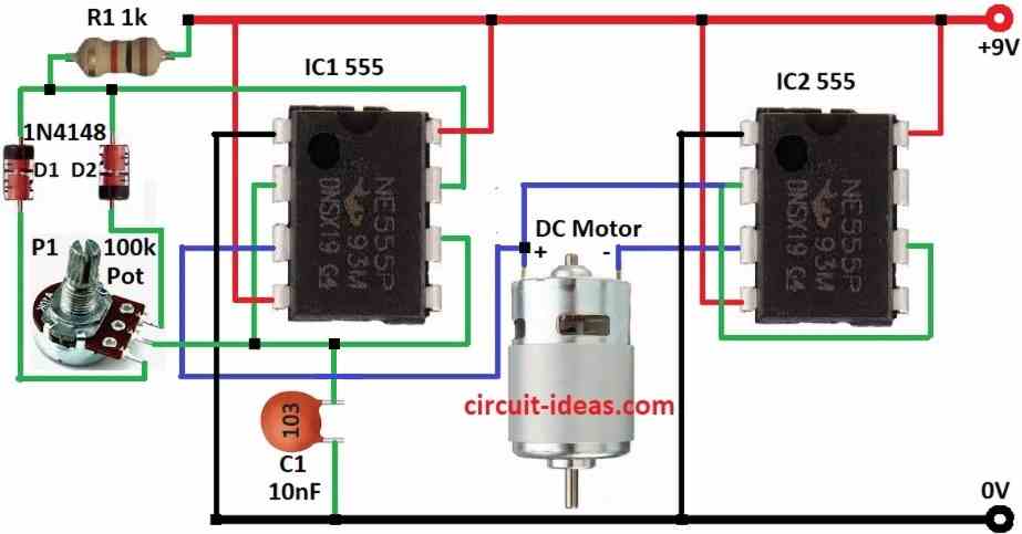
This H-Bridge PWM Driver Circuit uses an IC 555 to control the speed and direction of a DC motor; also the circuit operates without driver transistors.
Furthermore, motor connect direct to two IC 555 and moreover, motor speed and direction can also be change; so we can only use two IC 555 to control the motor
Therefore, this circuit offers a simple design and works well for small motor projects.
Circuit Working:
Parts List:
| Components | Values | Quantity |
|---|---|---|
| Resistor | 1k 1/4 watt | 1 |
| Potentiometer 100k | 1 | |
| Capacitor | Ceramic 10nF | 1 |
| Semiconductors | IC 555 | 2 |
| Diodes 1N4148 | 2 | |
| DC Motor | 1 |
To begin with, this circuit uses two IC 555 timers, shown as IC1 and IC2; IC1 generates a PWM signal and operates as an astable multivibrator.
Pin 3 of IC1 give PWM output and speed and signal duty change by R1, C1 and potentiometer which is the variable resistor.
After that, IC2 work like flip-flop (set-reset) and when IC1 pin 3 is high then IC2 pin 2 and pin 6 goes more than 2/3 VCC.
Then IC2 pin 3 goes low and motor turns clockwise.
When IC1 pin 3 is low then IC2 pin 2 and pin 6 goes less than 1/3 VCC and then IC2 pin 3 goes high and motor turn anti-clockwise.
Turning pot changes resistance and this changes C1 charge/discharge time and that change PWM duty cycle.
Motor is load and H-bridge setup control motor speed and direction and motor move clockwise or anti-clockwise by ON/OFF signal from IC1.
Hence, IC1 give PWM and duty cycle decide motor speed, so change potentiometer to adjust duty cycle and circuit run with 9V battery or power supply.
Formulas:
To control H-Bridge switch or DC motor speed we need to use IC 555 in astable mode and this makes PWM signal.
Below is formula:
Frequency (f):
How fast it switches depends on resistor R1, R2 and capacitor C.
Formula:
f = 1.44 / (R1 + 2R2) × C
- R1 and R2 connect to IC 555
- C is timing capacitor
Duty Cycle D:
Duty cycle mean how long output stay ON vs OFF.
Formula:
D = R2 / (R1 + 2R2)
Use this to make PWM signal for H-Bridge driver and this controls motor speed and direction.
How to Build:
To build a H-Bridge PWM Driver Circuit using IC 555 follow the below mentioned connections steps:
- First, take all parts as shown in diagram.
- Next, connect pin 1 of IC1 to ground.
- After that, connect pin 2 and pin 6 of IC1 together.
- Now, connect pin 3 of IC1 to positive side of DC motor.
- Then connect pin 4 of IC1 to 9V power and also connect pin 8 of IC1 to 9V supply.
- Connect pin 6 of IC1 again to pin 2 and connect pin 7 of IC1 to two diodes D1 and D2.
- Put capacitor C1 from pin 2/pin 6 to ground and connect middle leg of pot P1 to pin 2/pin 6 of IC1.
- Also, connect 1st and 3rd leg of pot P1 to each diode and then put resistor R1 between diodes D1 and D2 to 9V supply.
Connection of IC2 555:
- First, pin 1 of IC2 go to ground.
- Next, connect pin 2 and pin 6 of IC2 together.
- Then connect pin 3 of IC2 to negative side of DC motor.
- Now connect pin 4 and pin 8 of IC2 to 9V supply.
- Lastly, connect pin 6 again to pin 2.
Conclusion:
Overall, this H-Bridge PWM Driver Circuit using IC 555 control DC motor speed and direction using H-bridge and IC 555 PWM.
Also, it have some small problem in smooth direction change and current handling but it is good for learning, therefore for big motors or strong work better use special H-bridge driver IC.
Leave a Reply