This is Simple Infrared Fire Alarm Circuit for beginners.
It use infrared receiver sensor to detect fire heat or flame light.
When fire come close sensor output changes.
Then LED glow and buzzer makes sound.
This circuit is cheap and easy to make.
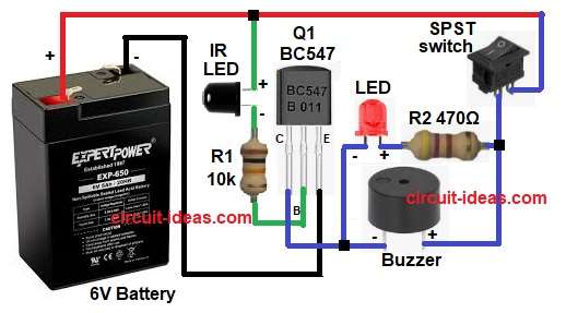
It also use only few parts like BC547 transistor, LED, buzzer, IR receiver LED , Resistors, SPST switch and 6V battery.
Circuit Working:
Parts List:
| Part Name | Quantity |
|---|---|
| Resistors | |
| 10k, 470Ω | 1 each |
| Semiconductors | |
| Transistor BC547 | 1 |
| LED any 5mm | 1 |
| Buzzer | 1 |
| Infrared photodiode LED | 1 |
| SPST Switch | 1 |
| 6V Battery | 1 |
Infrared receiver normally sense infrared light from fire or hot object.
When there is no fire the sensor output keep transistor OFF.
And LED and buzzer also stay OFF.
When fire is detected flame emit infrared.
Receiver detect this IR.
Receiver output drop or change.
This signal go to base of BC547 transistor.
The resistor makes the current small to protect a transistor and a LED.
Transistor turn ON and current flow from battery to LED and buzzer.
LED glow and buzzer make loud sound.
Alarm remains active until fire goes away.
Switch turn power ON and OFF.
ON means current flow.
OFF means no current flow.
Formula with Calculation:
Below is the transistor base current formula:
Ib = (Vsignal – 0.7) / Rb
where,
- Vsignal is sensor output voltage.
- 0.7 is base emitter drop of BC547.
- Rb is base resistor.
Collector current formula:
Ic = Beta * Ib
where,
- Beta is gain of BC547 usually 100 to 300.
Buzzer current fromula:
I = V / Rload
If buzzer take 20mA at 6V then circuit must allow same current through transistor.
LED resistor formula:
R = (Vbattery – Vled) / Iled
For example LED drop 2V, current 10mA and battery 6V
R = (6 – 2) / 0.01 = 400 ohm.
So we can use 390 or 470 ohm standard value resistor.
How to Build:
To build a Simple Infrared Fire Alarm Circuit follow the below steps:
- Take all the circuit parts as shown in circuit diagram.
- Connect IR photodiode to base pin of transistor through 10k resistor.
- Connect one buzzer wire to collector pin.
- Connect other buzzer wire to battery positive through switch.
- Put red LED and 470 ohms resistor in series.
- Connect this LED series part in parallel with buzzer.
- Add switch like shown in diagram.
- Connect emitter pin of transistor to battery negative.
- Connect battery and turn the switch ON.
Conclusion:
This Simple Infrared Fire Alarm Circuit is very easy project.
It detect flame using IR receiver.
It turn ON LED and buzzer when fire is near.
Good for school project and safety learning.
Easy to build with low cost parts.
Leave a Reply