Nowadays, light detector circuits are very useful in many small electronic projects, For example, we use them in automatic lamps, security alarms, and light sensing devices.
In this Simple LDR Based Light Detector Circuit using Timer 555 IC, the IC works as the main control unit, along with that, the CDS photocell, also called LDR (Light Dependent Resistor), senses the light intensity.
When the light level changes, the resistance of the LDR also changes, as a result, the 555 timer receives a different voltage signal and drives the speaker.
Therefore, the circuit can detect light and produce sound output, moreover this circuit is simple, low cost and easy to build for students and beginners.
Circuit Working:
Parts List:
| Components | Values | Quantity |
|---|---|---|
| Resistors | 47k, 1k, 10k | 1 each |
| LDR Light Dependent Resistor | 1 | |
| Capacitors | Ceramic 0.047µF | 1 |
| Electrolytic 4.7µF 25V | 1 | |
| Semiconductors | 555 Timer IC | 1 |
| Speaker 8Ω | 1 | |
| Power Supply 9V DC | 1 |
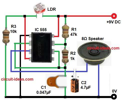
In the above circuit diagram, the LDR senses the surrounding light, in bright light the resistance of the LDR becomes low and on the other hand, in darkness the resistance becomes high.
Here, the 555 timer IC works in astable mode to generate pulse signals, the resistors R1 and R2 together with capacitor C1 decide the oscillation frequency.
Meanwhile, the LDR and resistor R3 create a voltage divider network and this network gives a control voltage to the 555 timer trigger and reset section.
When light falls on the LDR, its resistance changes immediately, consequently, the voltage at pin 4 and pin 7 changes and then the 555 timer starts generating pulses at pin 3, after that capacitor C2 couples the output signal to the 8Ω speaker.
Finally, the speaker produces a beep or tone and thus, whenever the light intensity changes the speaker sound also changes.
Formula with Calculation:
For a 555 timer in astable mode, the frequency formula is:
f = 1.44 / ((R1 + 2R2) × C1)
where,
- f is the frequency of output pulse in Hertz Hz
- 1.44 is constant value for 555 timer astable mode
- R1 is the first resistor value as 47k in our circuit.
- R2 is the second resistor value 1k in our circuit.
- C1 is the timing capacitor value 0.047µF
When we substitute the values:
R1 is 47k = 47000 ohm
R2 is 1k = 1000 ohm
C1 is 0.047uF = 0.047 × 10^-6 F
So,
f = 1.44 / ((47000 + 2 × 1000) × 0.047 × 10^-6)
f = 1.44 / (49000 × 0.047 × 10^-6)
f = 1.44 / (0.002303)
f = 625 Hz
Therefore, the speaker produces a tone of approximately 625 Hz.
How to Build:
To build a Simple LDR Based Light Detector Circuit using Timer 555 IC following are the steps we need to follow for connections:
- First, collect all components same like shown in above circuit diagram.
- Next, start from IC pin 1 and connect it direct to ground.
- Pin 2 connect with capacitor C1 and also join it with pin 6 of IC.
- Pin 3 is output pin and connect it to capacitor C2 and then connect to speaker and ground.
- Pin 4 connect to +9V positive power supply.
- Pin 7 connect in between resistor R1 and resistor R2.
- Pin 8 connect direct to +9V supply.
- Finally, connect LDR and resistor R3 in series connection between positive supply and ground.
Conclusion:
This Simple LDR Based Light Detector Circuit using Timer 555 IC is simple and effective project.
The LDR senses the light variation and quickly changes the timer response, as a result, the speaker gives an audible sound signal.
Moreover, the circuit uses very few components, so anyone can build it easily.
Therefore, it is a good project for beginners, school students and electronics hobby users.
Leave a Reply