Simple LED Driver Circuit using IC 7555 uses one special chip called as 7555 IC.
People mostly use it for timing but here we have used for different way.
It work like boss and control how electricity connects to LEDs.
Chip make special pulse signal like square wave and this signal connects to transistor which act like gate and open or closes for electricity.
So this way LED gets power nicely and stays bright.
Circuit Working:
Parts List:
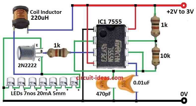
| Component | Description | Quantity |
|---|---|---|
| Resistors | 10k 1/4 watt | 1 |
| 1k 1/4 watt | 2 | |
| Capacitors | Ceramic 470pF | 1 |
| Ceramic 0.01µF | 1 | |
| Semiconductors | IC 7555 | 1 |
| Transistor 2N2222 | 1 | |
| LEDs 5mm 20mA | 7 | |
| Coil Inductor 20uH | 1 |
This easy LED driver circuit can power up to 7 LEDs using only one AAA battery.
It uses 220uH inductor to make voltage go much higher than the battery gives.
It needs good inductor with Q more than 90 or it does not work good.
If input is 1.25V and LEDs are ON then voltage pulse can go up to 23V.
The circuit uses 7555 timer chip which work nice with low voltage and it can run almost 190 hours on one 2000mAh NiMH battery.
This chip send fast signal to transistor like 222 kHz speed.
We can connect 7 LED groups in parallel but only if all LEDs have same forward voltage.
If some LEDs have lower voltage then they light up more and make other LEDs dim.
Parallel connection does not take more current from battery but LEDs look less bright.
With 1.25V battery whole LED group take around 8mA.
If input goes higher like 2.5V then current goes up to 20mA.
Formulas:
Below mentioned basic formula is used when building and checking circuit with 555 in Astable Mode.
555 Astable Mode:
Frequency (f):
f = 1.44 / ((R1 + 2×R2) × C)
where:
- R1 and R2 are resistors connected to 555 chip
- C is capacitor connected to same chip
Duty Cycle (D):
D = R2 / (R1 + 2×R2)
Boost Converter:
Output Voltage (Vo):
Vo = Vin / (1 – D)
where:
- Vin is input voltage
- D is duty cycle
Inductor Value (L):
L = (Vin × D × ton) / (ΔIL)
where:
Note:
To make this circuit work better we need to do these calculations again and again and try different values to get good result.
How to Build:
To build a Simple LED Driver Circuit using IC 7555 we need to follow the below mentioned assembling steps:
How to Connect the Circuit:
- Connect positive side of AAA battery to pin 8 of 7555 IC.
- Connect pin 1 of 7555 IC to battery negative side ground.
- Pin 4 of 7555 also is connected to battery positive.
- Join pin 2 and pin 6 together and then connect them to pin 7 using 10k resistor.
- Also put 1k resistor from pin 7 to battery positive.
- Connect pin 5 to ground with 0.01µF capacitor.
- Pin 3 connects to base of 2N2222 NPN transistor through 1k resistor.
- Emitter of transistor connects to ground.
- Collector of transistor connect to one side of 220uH coil inductor.
- Other side of inductor connects to anode positive leg of 7 LEDs.
- Cathode negative leg of LEDs connects to ground.
For Multiple LED Groups:
- If using many LED groups connect them in parallel.
- Be sure all LEDs have same forward voltage and if not then some LEDs will shine less.
Power and Test:
- Use AAA cell to power circuit.
- Check if LEDs light up good and if some look dim then maybe forward voltages does not match.
Adjustments:
- We can change resistor values to get more or less brightness and better efficiency.
Important Note:
- Building circuits need some basic electronics knowledge and safety.
- If not then be sure and ask someone who knows or get help from expert.
Conclusion:
This Simple LED Driver Circuit using IC 7555 is easy and works well for powering one or more LEDs.
The 7555 IC set in astable mode so it make square wave signal and this signal turn the LEDs ON and OFF with fixed speed.
The circuit is simple to make and can change for different LED uses.
But very important to pick correct resistor and capacitor for 7555 IC.
This help get right frequency and duty cycle to run LEDs properly.
In total this LED driver using 7555 is cheap, easy and good for many small lighting projects.
Leave a Reply