This Simple Shadow Detector Security Circuit is like one guard with very sharp eyes.
It uses one light sensor like photodiode to look shadow in one place.
If something stop the light and make shadow then the circuit think someone is there and start an alarm.
Alarm can be loud sound, blinking light or something to indicate one.
This type of circuit is good for security because it sees movement without big camera or costly sensor.
So if anyone want to watch their place, this circuit will help them by turning shadow into warning!
Circuit Working:
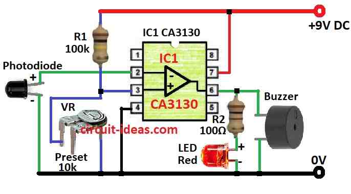
Parts List:
| Component Type | Description | Quantity |
|---|---|---|
| Resistors | 100k | 1 |
| 100Ω | 1 | |
| Preset 10k | 1 | |
| Semiconductors | IC CA3130 | 1 |
| Buzzer | 1 | |
| LED Red 5mm 20mA | 1 | |
| Photodiode | 1 |
This shadow alarm circuit sees movement in small area using light sensor called PIN photodiode.
It can help stop thief by making loud sound when someone come near.
The circuit works because photodiode make small current when light fall on it and it is forward biased.
IC1 is voltage checker as a comparator its pin 3 at non-inverting input connects to resistor R1 and VR (a variable resistor) to make fixed voltage.
By turning VR we can set how much voltage goes to pin 3.
Photodiode is connected to pin 2 at inverting input of IC1.
This IC called CA 3130 is fast op-amp with special MOSFET inside so it works good even with very small current.
It has high input resistance and very small input current like 10 picoamps so it is very fast and looks good for low current jobs.
CA 3130A and CA 3130 are mix CMOS and bipolar tech.
Its input part have special MOSFETs that give very high resistance, low current and fast speed.
Also it can work with input voltage that goes almost to negative supply which is good for single battery use
Its output part goes very close to both power lines but there should be only 10mV gap so one can get almost full swing voltage out.
This IC works with 5V to 16V power which needs only one capacitor for phase setup and can adjust offset if needed.
Now under normal light as set by VR, photodiode send voltage to pin 2 of IC1.
This voltage is more than voltage at pin 3 which is set by VR so output of IC1 is low and buzzer and LED stay OFF.
But when someone comes close and make shadow on photodiode, light drop, current drop and voltage at pin 2 goes down.
Now voltage at pin 2 is less than pin 3 so output of IC1 goes high and buzzer turn ON to give alarm.
Formula:
In this shadow alarm circuit we have used one CA 3130 op-amp and one photodiode to find change in light.
These parts help circuit know if light goes down like when shadow comes, then it makes sound for alarm.
Exact math for this circuit depend on how we want alarm to work.
But some general formulas can help understand how circuit works.
Voltage divider formula (for resistors):
This formula help find reference voltage for op-amp.
It tells how much voltage come out from middle point between two resistors:
Vout = Vin × (R2 / (R1 + R2))
where,
- Vout is voltage at output of resistor divider
- Vin is voltage coming into resistor divider
- R1 and R2 are the two resistor values
This formula help decide voltage going to one pin of op-amp.
Comparator formula for op-amp:
In this circuit op-amp work like comparator.
It look at two voltages one from photodiode and one from VR (reference voltage).
If voltage from photodiode at pin 2 is less than voltage at pin 3 then output goes high with an alarm ON.
If voltage at pin 2 is more than pin 3 then output stay low with an alarm OFF.
Not exact big formula here but comparator only check which voltage is higher.
Output goes ON or OFF depending on that.
So this simple math help anyone know what circuit decide when to turn alarm ON or OFF using light and shadow.
How to Build:
To build a Simple Shadow Detector Security Alarm Circuit follow the below steps:
Power Connection:
- Connect power supply like below:
- Positive (+) wire connects to pin 8 VCC of CA 3130 IC
- Negative (–) wire connects to pin 4 ground
Set Reference Voltage:
- Connect pin 3 non-inverting input to a resistor divider:
- Use R1 100k and VR 10k preset
- Turn VR to change the reference voltage for setting light level
Photodiode Connection:
- Connect anode positive leg of photodiode to pin 2 of inverting input of IC
- Connect cathode negative leg of photodiode to ground
Output Connection:
- Connect pin 6 output of IC to LED anode
- Put a 100Ω resistor R2 in line to protect LED
- Connect buzzers negative pin to ground
- Power ON the circuit
- In normal light LED stays OFF means photodiode getting enough light
- When we build shadow on photodiode, LED turns ON and buzzer makes sound when the circuit sees the shadow
Adjustment:
- If the circuit is too sensitive or not working well then turn VR preset to change light trigger level
- This help set when alarm should turn ON
Note:
- Circuit works by seeing change in light
- Not only shadows but any drop in light can trigger it
- Best to keep it in place where light stays same where there is no flickering or changes.
Conclusion:
This Simple Shadow Detector Security Alarm Circuit is very useful in security.
It uses light sensor to see shadow and give and alarm alert when something moves or someone comes.
This help warn people if there is intruder or any wrong movement.