Simple UJT LED Flasher Circuit is very simple way to make LED blink ON and OFF, as it uses special transistor name UJT which one work like small flasher switch.
Here, UJT give pulse electric and make LED ON and OFF again and again with same time always; also this circuit is good for fun DIY project where one can use for decoration blink or learn electronic in cool way.
Circuit Working:
Parts List:
| Components | Values | Quantity |
|---|---|---|
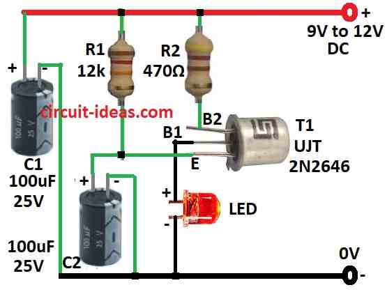
| Resistors | 12k 1/4 watt | 1 |
| 470Ω 1/4 watt | 1 | |
| Capacitors | Electrolytic 100µF 25V | 2 |
| Semiconductors | UJT 2N2646 | 1 |
| LED 5mm 20mA | 1 |
This simple UJT LED flasher look like real alarm system which helps for better security, also one can put it on door, gate or car, it confuses thief or bad guy.
Circuit is not hard, it uses one special part UJT transistor and this UJT work like flasher and make light blink.
UJT mean Unijunction Transistor which have one junction and three legs: Emitter (E), Base1 (B1) and Base2 (B2).
Inside, an N-type bar features two ends B1 and B2, while an emitter sits in the middle P-type region.
Between B1 and B2 when there is no power supply to emitter we call that resistance inter-base resistance, also one popular UJT is 2N2646.
We give power to both bases make voltage drop along it and when emitter get enough voltage like more than one diode drop it start to give current to base area.
Furthermore, this extra current make base area more conduct so resistance goes down and that make emitter provide even more current.
Therefore, resistance drops again, causing a phenomenon called negative resistance and this property allows the UJT to function effectively in simple oscillator circuits that generate repeating pulses.
In this UJT LED flasher 2N2646 UJT work like small oscillator.
Parts R1 and C2 help make timing and LED connect between B2 and ground, resistor R2 stop too much current going to UJT and LED.
When power is ON capacitor C2 charge with help of R1 and when C2 is full, emitter gets power to turn ON UJT through which the current goes to base and then LED blinks.
After that C2 gets empty and then charges again and this cycle keeps on going and LED will keep on blinking.
Formulas:
The formula for the UJT LED Flasher Circuit appears below:
Charging Time (T):
How fast capacitor C1 charges will decide how fast LED blinks and we can find charging time like this:
T = 0.7 * RB1 * C1
where:
- RB1 is the resistor between B1 and power positive.
- C1 is the capacitor between B2 and ground.
Frequency (f):
How fast LED blinks frequency is opposite of charging time:
f = 1 / T = 1 / (0.7 × RB1 × C1)
So small T means fast blinking and big T means slow blinking.
LED Resistor (RL):
We must choose resistor for LED so it does not burn and for that use this formula:
RL = (VCC − VLED) / ILED
where:
- VCC is power supply example: 9V
- VLED is LED forward voltage which means how much voltage LED need
- ILED is how much current LED need which is usually 20mA
By using these formula one can make UJT LED flasher that blink LED at timing one wants, also change RB1 and C1 to make LED blink slower or faster.
Test the circuit to get good results and be sure all works fine.
How to Build:
Below are the steps to build a Simple UJT LED Flasher Circuit:
Connect the UJT:
- First, put 2N2646 UJT on breadboard and connect LED between B1 pin of UJT and ground.
- Next, take 470Ω resistor R2 and connect it between B2 of UJT and positive power.
- Then take 10k resistor R1 and connect it between emitter (E) of UJT and positive power.
- After that, connect 100µF capacitor C2 between emitter of UJT and ground.
Power Supply:
- Now connect positive wire of power to breadboard positive rail and connect negative wire of power to breadboard ground rail.
- First, check all wires and parts and be sure everything connected is correct and turn ON the power; if all is working good then LED will start blinking like fake alarm light.
Important Notes:
- Check again all connections and part values before putting the power ON, wrong design can break parts.
- Use correct power and connect wires with right direction polarity and we can change R1, R2 or C2 to make LED blink faster or slower.
Conclusion:
Overall, Simple UJT LED Flasher Circuit uses Unijunction Transistor to make LED blink ON and OFF again and again.
Also, this circuit is simple, cheap and easy to build and we can use it for many things like DIY project, decoration lights or learning electronics.
Leave a Reply