This simple article is for Two Star Flasher Circuit with 555 IC and its main part is 555 timer IC which works in astable mode; also in this mode IC give continuous square wave pulses.
These pulses make the two lamps blink alternately, creating a star-like flashing effect; also the resistor and capacitor values show the blinking speed.
Since the 555 IC cannot drive the lamps directly, the circuit uses transistors to drive the relay.
Circuit Working:
Parts List:
| Components | Values | Quantity |
|---|---|---|
| Resistors | 15k 1/4 watt | 1 |
| 1k 1/4 watt | 1 | |
| Preset 100k | 1 | |
| Capacitor | Electrolytic 100uF 25V | 1 |
| Semiconductors | IC 555 | 1 |
| Transistor BC547 | 1 | |
| Diode 1N4007 | 1 | |
| Relay 12V SPDT | 1 | |
| Any LED bulbs of 230V | 2 |
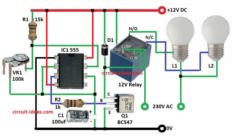
The circuit operates on a +12V DC supply, also its main component is the 555 IC, which works in astable mode and generates continuous pulses.
R1, VR1 and C1 show the blinking speed, while the VR1 preset adjusts the ON and OFF timing of the light.
Since pin 3 cannot supply enough current to drive the relay directly, the circuit uses a BC547 transistor as a relay driver.
When output is high then transistor is ON, relay is ON and one lamp glows and other is OFF and when output is low then transistor is OFF, relay is OFF with contact change and other lamp glows.
So lamp L1 and L2 blink one by one and then diode 1N4007 protect from relay back emf.
Formulas:
The formula for Time period T of oscillation is:
T = 0.693 * (R1 + 2VR1) * C1 seconds
High time = 0.693 * (R1 + VR1) * C1
Low time = 0.693 * VR1 * C1
Frequency f = 1 / T
here,
- R1 is 15k
- VR1 is 100k
- C1 is 100uF
T = 0.693 * (15000 + 2*100000) * 0.0001
= 0.693 * 215000 * 0.0001
= 14.9 seconds approx
So frequency = 1 / 14.9 = 0.067 Hz approx
This means the relay switches approximately once every 15 seconds and if we need faster flashing, reduce the value of VR1 or C1.
How to Build:
To build a Two Star Flasher Circuit with 555 IC follow the below steps for connections:
- First, collect all parts same like circuit diagram.
- Next, pin 1 of IC 555 goes to ground.
- After that, pin 2 and pin 6 connect with VR1 and capacitor C1.
- Then pin 3 connects to base of transistor Q1 by resistor R2.
- Now pin 4 and pin 8 goes to +12 DC supply.
- Also, pin 7 connect between VR1 and resistor R1.
- Further, collector of Q1 connect to one coil pin of relay and then diode D1 anode connect to collector and relay coil and cathode to +12V DC and other coil pin of relay goes to +12 DC.
- Finally, lamp L1 and L2 connect to 230V AC by relay contacts.
Conclusion:
Overall, this Two Star Flasher Circuit with a 555 IC and relay is a simple project that creates decorative lighting effects for signboards, party decorations and other visual displays.
We can also change resistor or capacitor to control flashing speed and this circuit is cheap and easy to build on small PCB or normal board.
Leave a Reply