In this post, the Hall Effect Sensor Circuit with IC LM393 detects a magnetic field and gives an output when a magnet comes near the sensor.
The module uses an LM393 comparator to provide a digital output, it also supports motor speed detection, position detection and security system applications.
Circuit Working:
Parts List:
| Components | Values | Quantity |
|---|---|---|
| Resistors | 1k 1/4 watt | 6 |
| Potentiometer 10k | 1 | |
| Capacitors | Ceramic 0.1μF | 2 |
| Semiconductors | IC Comparator LM393 | 1 |
| Any LED | 2 | |
| Hall Effect Sensor Module | 1 | |
| 4 pin Connector | 1 |
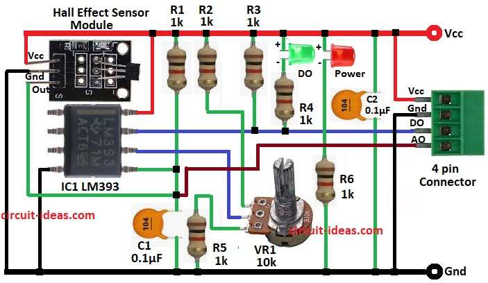
The Hall sensor has three pins: Pin 1 VCC, Pin 2 GND, Pin 3 OUT.
When a magnetic field comes near, the sensor generates a small voltage change; the LM393 comparator compares this sensor signal with the reference voltage set by the 10 kΩ potentiometer.
If the sensor signal exceeds the reference value, the comparator changes its output state and the DO LED glows when it detects a magnet.
Another LED PWR shows power supply.
Formulas:
Comparator output depends on input voltage difference.
Vout = High if Vin+ > Vin-
Vout = Low if Vin+ < Vin-
Reference voltage set by potentiometer is:
Vref = (R2 / (R1 + R2)) * Vcc
here,
- R1 and R2 are parts of potentiometer division.
For example with 10k pot and Vcc = 5V
Vref adjusted between 0V and 5V.
Output current for LED = (Vcc – Vf) / R
- Vcc is supply voltage for example 5V
- Vf is forward voltage drop of LED which is around 2V for red LED and 3V for white/blue LED
- R is series resistor for example 1k in diagram
- I is LED current in amperes A
So the resistor controls how much current flows through the LED.
How to Build:
To build a Hall Effect Sensor Circuit with IC LM393 follow the below mentioned steps:
- First, assemble all the circuit parts as shown in diagram above.
- Next, Hall Sensor Pin 1 VCC to +5V supply, Hall Sensor Pin 2 GND to Ground and Hall Sensor Pin 3 OUT goes to comparator input pin 5
- Then LM393 pin 8 to VCC
- Also, LM393 pin 4 to Ground
- After that, pin 5 connected to Hall sensor output pin.
- Now pin 6 connected to potentiometer reference and pin 7 comparator output connected to LED DO and module output pin
- Further, capacitors 0.1uF used for noise filter and resistors 1k used for current limiting to LEDs
- Finally, connector with 7 pins: Pin 1 AO Analog Output, Pin 2 DO Digital Output, Pin 3 GND, Pin 4 VCC connect as per circuit diagram above.
Conclusion:
Overall, Hall Effect Sensor Circuit with IC LM393 is easy to use, it detects magnet presence.
The circuit provides digital and analog outputs and the potentiometer adjusts the sensitivity; therefore, the circuit is useful for motor speed control, magnetic switches and automation projects.
Leave a Reply