In this post for Motorcycle LED Turn Signal Indicator Circuit the LED flashes with chasing effect, instead of old bulb type and IC 555 works like oscillator and gives flashing signal.
Circuit Working:
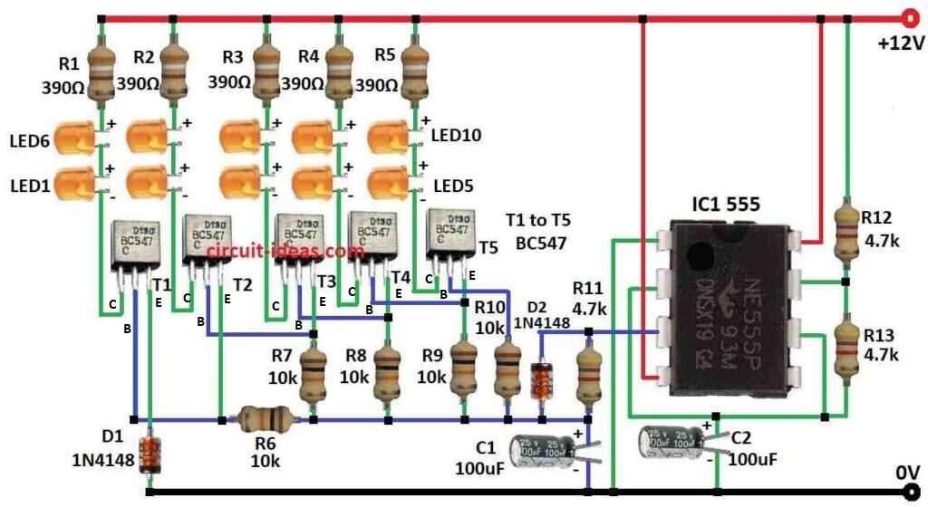
Parts List:
| Components | Values | Quantity |
|---|---|---|
| Resistors | 390Ω 1/4 watt | 5 |
| 10k 1/4 watt | 5 | |
| 4.7k 1/4 watt | 3 | |
| Capacitors | Electrolytic 100μF 25V | 2 |
| Semiconductors | IC 555 | 1 |
| Transistors BC547 | 5 | |
| LEDs Orange 5mm 20mA | 10 | |
| Diodes 1N4148 | 2 |
To begin with, this simple motorbike LED turn-signal circuit uses an IC 555 configured as an astable multivibrator to generate a flashing signal.
How it works:
A 12V motorbike battery powers the circuit, the main component is IC 555, where IC1 operates in astable mode and it does not require a trigger signal and continuously generates pulses.”
Furthermore, C2 capacitor and R12 resistor control how fast it flash and when power is ON then C2 charge through R12.
As the voltage on C2 rises, pin 3 outputs a LOW signal (logic 0) and when C2 becomes fully charged, pin 3 changes its output to a HIGH signal (logic 1).
Then C2 discharge again through R12 resistor and voltage goes down and when voltage drop low again then output goes back to LOW.
With this up-down repeat, so LED keep blinking.
Moreover, transistors T1 to T5 work like switches and control LED current and then they turn ON one by one and make LED run in chasing style.
Also, diodes D1 and D2 protect transistors from voltage spike and resistors R1 to R13 limit current and set voltage at places in circuit.
Formulas:
Using IC 555 we can make astable multivibrator circuit for motorbike LED turn signal, also this circuit switch between two states left and right with fixed speed.
Formula for Frequency (f):
How fast it blink depends on resistor R1, R2 and capacitor C.
f = 1.44 / (R1 + 2R2) × C
where,
- R1 and R2 connect to IC 555
- C is timing capacitor
Duty Cycle D:
Duty cycle means how long output stay ON high vs OFF low.
D = R2 / (R1 + 2R2)
Change R1, R2 and C to make blink speed right for our motorbike turn signal circuit
How to Build:
To build a Motorcycle LED Turn Signal Indicator Circuit follow the below mentioned steps for connections:
- First, collect all parts as shown in circuit diagram above.
- Next, connect pin 1 of IC 555 to ground.
- Join pin 2 and pin 6 together and then connect capacitor C2 from this point to ground.
- Then connect pin 3 to ground through resistor R11 and capacitor C1.
- Now connect pin 4 and pin 8 of IC to 12V power.
- Place resistor R13 between pin 6 and pin 7 and then connect pin 7 to 12V through resistor R12.
- After that, connect R1 to R5 resistors and LED1 to LED10 in sequence to collector of transistors T1 to T5.
- Also, connect emitter of T1 to ground through diode D1 and then connect emitters of T2 to T5 to IC pin 3 output through resistors R6 to R10.
Safety Tips:
- Use correct resistor values for LEDs or LEDs may burn, also check all wires and parts before power ON.
- Circuit is simple and may not work for all motorbikes, so better to let electrician install it safely.
Conclusion:
To conclude, this Motorcycle LED Turn Signal Indicator Circuit is better than old bulb type which are brighter, longer life and with less power; but for safe use we must check motorbike compatibility and use LED flasher relay and install it carefully.
Leave a Reply