Christmas come one time in a year and it brings big joy.
The Simple Christmas Series Lights Tester Circuit is an easy to build design that helps us find and fix problems in series Christmas lights, also people commonly use these lights for holiday decorations.
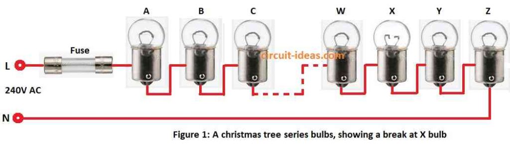
If one bulb stops then all lights go OFF, as one bad bulb break the whole circuit and makes the string dark.
Below is the circuit diagram that show how it work and how to make it.
Circuit Working:
The circuit shown above is simple to build, it helps us find a faulty bulb quickly without removing all the bulbs or doing a lot of manual work.
This tool is useful for the whole year which test the fuse, lamp, wire and more.
A wire, such as one in a Christmas light string, creates an electric field when we plug it in, even when no current flows, the field remains present even if the wire breaks.
Hence, this circuit also helps us locate the point where the break occurs.
In fig 1 lights connect to power and breaks at point X with bulb bad or loose.
From live terminal, the field is at A, B, C… till X and at X there is no field that show problem spot, then just check the bulb clean it or push it in.
If many bulbs fail, the tester identifies the first faulty bulb and after we fix it, we can easily find the next faulty bulb.
However, a small problem remains: the manufacturer does not always space the wires evenly inside the light string.
Neutral wire wrap around live wire which is hard to test one alone and if plug in right way then live wire makes field.
Neutral wire is close to ground with weak field and the tester mostly feels the live wire.
If neutral wire break means the rare, then its is still light or socket problem and if there is break at point X then wires on left show field and right side show nothing which means neutral.
If we reverse the plug from L–N to N–L, the electric field appears along the entire wire, even if the wire has a break, the tester still detects the full electric field.
Both wires usually green which are hard to know which is live and if light is not working but field is everywhere then flip plug or rewire it.
Detecting electric fields:
Parts List:
| Components | Values | Quantity |
|---|---|---|
| Resistors | 1k 1/4 watt | 1 |
| 100Ω 1/4 watt | 1 | |
| Semiconductors | Transistor BC547 | 2 |
| Transistor BC557 | 1 | |
| LED any 5mm 20mA | 1 |
We can find the electric field by using a metal wire or plate as a probe, also the probe acquires the same voltage as the field at that location.
If voltage is AC then field can also change back and forth, but it is hard to show this with normal tools.
If we use a normal voltmeter with a probe and ground, it shows no reading and may overload the meter, so to fix this, we use a high-input-impedance buffer or amplifier to display the result.
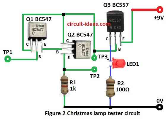
Also, this circuit uses strong amplifier with high input impedance, with only 3 transistors, 2 resistors and 1 LED see the fig 2.
First two transistors make Darlington pair and this gives big current gain to about 10,000 and input impedance is about 10 megohms.
Current then goes to PNP transistor which turns ON the LED.
Want sound too? then we can add piezo buzzer, then circuit works with voltage as low as 3V, so use 9V battery or two 1.5V AAA cells,
At low voltage, the buzzer produces a weak sound and consumes very little power, therefore, we do not need an ON/OFF switch, and the battery lasts much longer.
Formulas:
Simple Christmas Lights Tester with easy formulas
Voltage at TP2 (Voltage Divider):
R1 1k and base-emitter of Q2 BC547 make voltage divider.
Voltage at TP2:
VTP2 = VTP1 − VBE
where:
- VTP1 is the voltage from lamp terminal
- VBE is the base-emitter voltage of Q2 is 0.7V
LED Current ILED:
Current through LED depends on resistor R2 100Ω and voltage drop:
ILED = (VTP3 − VLED) / R2
where:
- VTP3 is the voltage at TP3
- VLED is LED forward voltage for 2V
Transistor Saturation:
To make Q1, Q2, Q3 go into saturation:
IB = IC / β
where:
- IB is the base current
- IC is the collector current like LED or R2 current
- β is the gain of transistor with 100 to 300 for BC547/BC557
How to Build:
To build a Simple Christmas Series Lights Tester Circuit following are the steps to follow:
- First, gather all parts as per fig 2 circuit diagram.
- Next, connect base of Q1 to TP1 tester, connect collector of Q1 to collector of Q2 and then connect emitter of Q1 to base of Q2.
- Now connect base of Q2 to emitter of Q1 which is the Darlington pair, connect collectors of Q1 & Q2 to base of Q3 and then connect emitter of Q2 to GND through R1 resistor.
- After that, connect collector of Q3 to GND through LED1 and R2, connect emitter of Q3 to +9V supply.
- Then TP2 tester goes between emitter of Q2 and R2 and then TP3 tester connects to base of Q3.
Safety Precautions:
- Be sure the tester works with AC or DC type light string.
- Unplug light string from wall before testing and avoid electric shock.
Conclusion:
To conclude, Simple Christmas Series Lights Tester Circuit is helpful tool, it finds bad bulbs or broken wires in series light strings.
Furthermore, it helps us fix lights fast while decorating.
Finally, this circuit uses low voltage which is safe to use while getting ready for holidays.
Leave a Reply