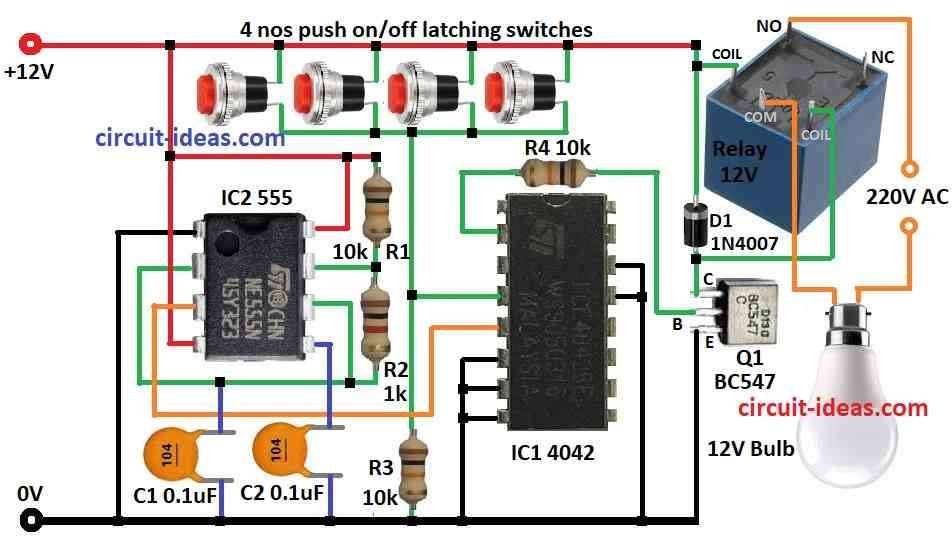
We can control one bulb from many places using Basic Circuit for Multi-Way Lamp Switching.
Three-way switches are also called two-way and four-way switches are also called intermediate which are also used.
Three-way switches go at both ends like at hallway doors.
They have 3 terminals: Traveler 1, Traveler 2 and Common.
Four-way switches go in between the two three-way switches.
They just change path of traveler wires and have 2 terminals.
Circuit Working:

Parts List:
| Category | Item | Quantity |
|---|---|---|
| Resistors | 10k 1/4 watt | 3 |
| 1k 1/4 watt | 1 | |
| Capacitors | Ceramic 0.1μF | 2 |
| Semiconductors | IC 555 | 1 |
| IC 4042 | 1 | |
| Transistor BC547 | 1 | |
| Diode 1N4007 | 1 | |
| 12V Relay | 1 | |
| Push ON/OFF latching switch | 4 | |
| 12V Bulb | 1 |
This circuit shows a new way to do multi-way switching.
Normally we can use simple wires but here we used IC 4042.
We used 4 buttons in 4 places to control one AC light.
IC 4042 can latch 4 outputs when it gets clock pulse.
Instead of normal switches we used one flip-flop inside IC 4042.
IC 4042 gets steady clock signal from 555 timer IC in astable mode.
IC 4042 has:
- 4 output pins like Q0, Q1, Q2, Q3
- 4 inverted outputs like Q0, Q1, Q2, Q3
- 4 data pins like D0, D1, D2, D3
- We only use D0, Q0 and Q0 in this design.
When D0 gets signal from switch then IC flips:
- Q0 goes LOW
- Q0 goes HIGH
Q0 HIGH turns on relay module and light turns ON.
Light stays ON until switch is pressed again.
Any of 4 buttons and all connected to D0 can turn light ON or OFF.
This gives control from many places which is very useful.
Formulas:
This circuit uses IC 555 as astable multivibrator for multi-way bulb control.
IC 555 gives square wave signal to control IC 4042.
Frequency formula:
f = 1.44 / (R1 + 2×R2) × C1
where,
- R1 and R2 are the resistors 1kΩ and 10kΩ
- C1 is the capacitor 0.1μF
Duty Cycle formula:
Duty = R2 / (R1 + 2×R2)
This means how long output stays HIGH in one cycle.
This square wave signal is used for switching the lamp in multi-way system.
We can change R1, R2 or C1 to adjust speed and duty as needed.
How to Build:
To build a Basic Circuit for Multi-Way Lamp Switching follow the below mentioned steps for connections:
- Connect pin 2 of IC1 4042 to the base of Q1 through R4
- Connect pin 4 of IC1 between R3 and 4 switches
- Connect pin 5 of IC1 to pin 3 of IC2 555
- Connect pins 6, 7, 8, 13, 14 of IC1 to ground
- Connect pin 1 of IC2 to ground
- Connect pin 2 to pin 6 of IC2 through C1
- Connect pin 3 of IC2 and pin 5 of IC1
- Connect pin 4 and pin 8 of IC2 to +12V supply
- Connect R2 between pin 6 and pin 7 of IC2
- Connect R1 from pin 7 to +12V supply
- All 4 switches should be in parallel
- Connect one end junction of R3 and pin 4 of IC1
- And other end connect to +12V
Relay Connection:
- Connect one coil end collector of Q1 through D1
- And other coil end connect to one end of 12V bulb
- NO (Normally Open) pin of relay connects to 220V AC
- Other end of bulb connects to 220V AC.
Benefits of Multi-Way Switching:
Convenience: Turn ON/OFF light from many places like hallway or room.
Safety: No need to walk in dark to turn ON the light.
Ambience: Control different lights from different spots.
Safety Tips:
- Wiring this is harder than normal switch.
- If not sure then ask an electrician for help.
- Follow local wiring rules like know power, neutral and traveler wires.
- Double check all wires before turning ON the power.
Conclusion:
This Basic Circuit for Multi-Way Lamp Switching uses IC 4042 + relay for smart multi-way switching.
Just press any one switch to turn light ON/OFF from many locations.
No need to hold the switch, just one press is required.
Leave a Reply