This Fast Charger Circuit with Auto Cut Off is fast charger for battery like car battery or backup battery.
It charges battery very quick but there is no need worry it wont overcharge.
Inside circuit there are have safety part when the battery is full it stops charging by itself.
This helps battery stay good and live longer.
So we can use it again fast for car or other things which need power.
Circuit Working:
Parts List:
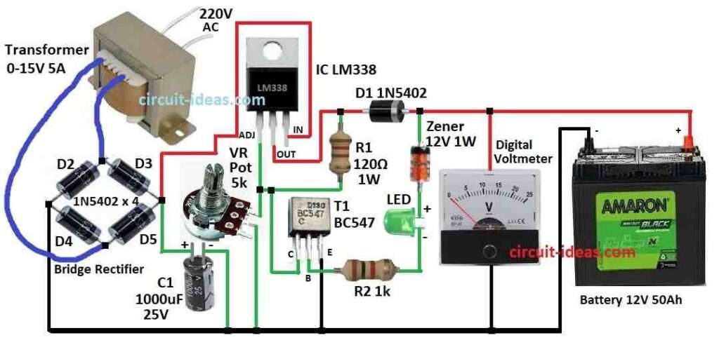
| Category | Component | Quantity |
|---|---|---|
| Resistors | 120Ω 1W | 1 |
| 1k 1/4 watt | 1 | |
| Potentiometer 5k | 1 | |
| Capacitor | Electrolytic 1000µF 25V | 1 |
| Semiconductors | IC LM338 | 1 |
| Transistor BC547 | 1 | |
| LED Green 5mm 20mA | 1 | |
| Zener diode 12V 1W | 1 | |
| Diode 1N5402 | 1 | |
| Bridge Rectifier 1N5402 | 4 | |
| Digital Voltmeter | 1 | |
| Transformer 0-15V 5 Amp | 1 | |
| Battery 12V 50Ah | 1 |
This circuit made to fast charge sealed lead acid battery.
It is used in car, inverter and more which gives big current around 5 amp and so battery charges fast.
It have one adjustable voltage part so can charge 6V and 12V battery both.
When battery is full it charger stop by itself with no overcharge problem.
Main part is LM338 is strong voltage regulator it gives 2V to 25V DC and high current.
Good things is it gives 7 amp peak output which goes low as 1.2V and protects from heat.
It is very easy to use and only needs two resistors to set output voltage.
Also it can give up to 12 Amp for short time which is good for fast startup and heavy load.
But LM338 get hot so need of heat sink for cooling.
To set voltage use two resistors one is R1 of 120 ohm which is called program resistor.
It uses 1.25V reference voltage between output and adjust pin.
This voltage goes across R1 to keep current same.
Then VR1 set output voltage where we can use formula to calculate this voltage.
Input voltage come from 0-15V 5A transformer and 10A KBPC rectifier.
One capacitor C1 remove ripple and gives around 16V DC to LM338.
VR variable resistor helps to adjust output from 2V to 15V.
Use digital panel meter to check voltage and connect meter to output.
Change VR to see voltage on meter.
If voltage drops from AC line then meter show it.
Meter also show battery voltage when there is no power.
If reading is same and steady battery will be full and good.
Auto cut-off part use 5A darlington NPN transistor BC547.
When battery goes above 12.5V Zener diode turn ON and stop LM338.
When battery goes below 12V Zener turn OFF and LM338 start again.
For 12V battery full charge is 13.5V and for 6V battery it is 6.5V.
Set charge voltage to 14V for 12V battery and 8V for 6V battery.
Use thick red and black wires with crocodile clips for battery connection and check polarity before connection.
Before plugins into wall power, connect clips to battery and check the voltage.
If battery voltage is less than 13.5 or 6.5 then turn on the charger and wait up to 1 hour.
After that wait for 10 minutes and check voltage again.
If voltage is steady then battery is ready to use.
Formulas and Calculations:
Here is some main formula and important things to remember when making fast battery charger with auto cut off using LM338 voltage regulator and other parts:
Voltage Control with LM338:
LM338 use outside resistors to give set voltage.
Formula for output voltage:
Vout = Vref × (1 + R2 / R1) + Iadj × R2
where,
- Vref is fixed voltage from LM338 which is usually 1.25V
- R1 and R2 are outside resistors we can connect to set output voltage
- Iadj is very small current about 50μA which mostly we can ignore it
Controlling Charging Current:
We can use extra transistor like BC547 if charging current is too high for LM338 alone.
To find charging current going to battery see the following formula:
Icharge = (Vout − Vbattery) / Rsense
where,
- Vbattery is battery voltage
- Rsense is small resistor connected in line to measure current
How to Build:
To build a Fast Charger Circuit with Auto Cut Off follow the below mentioned connections steps:
- Connect transformer secondary side to KBPC rectifier which gives 0 to 15V DC output.
- Connect Vin input of LM338 to DC from rectifier.
- Connect Vout output to battery.
- Use two resistors R1 and VR1 to set output voltage of LM338.
- Check LM338 datasheet to get correct resistor values.
- Use Zener diode and BC547 Darlington NPN transistor and connect same like in auto cut-off diagram.
- Connect digital meter to output to show battery voltage during charging.
Steps to Follow:
- Put all parts on PCB or breadboard.
- Follow circuit diagram for correct wiring.
- Be sure wires and polarity are correct.
- Give power from transformer positive rectifier.
- Use VR1 to adjust output voltage for charging.
- Use crocodile clips to connect battery.
- Watch charging on digital meter.
- When battery is full auto cut-off will stop charging.
Safety Tips:
- Use good insulation on wires.
- Connect proper heat sink to LM338.
- Check all wires twice before turning ON.
- Do not leave charger running without watching.
- Be careful we are working with high voltage and current.
Important Note:
- This circuit is for learning purpose only.
- Follow local safety rules if using for actual circuit.
- We may need to change parts like resistors, capacitor or transformer if based on what battery we need to use and parts we are having
Conclusion:
Fast Charger Circuit with Auto Cut Off is useful and smart way to charge battery fast and safe.
It stops charging when battery is full so there is no overcharge happen.
This circuit uses LM338 voltage regulator with auto cut off circuit and is with adjustable voltage divider.
It can charge many types of batteries like car battery, inverter battery and more very well and safely..