Simple IC 555 Oscillator Circuits is a 555 timer chip which is common and easy to use; also it is good for many projects.
But for some circuits we must know how it works when not active.
Two main pins:
- Pin 6 (upper threshold)
- Pin 2 (lower threshold)
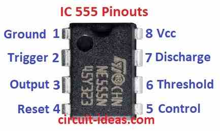
IC 555 Pinouts
Here is a list that shows what each pin on the chip does.
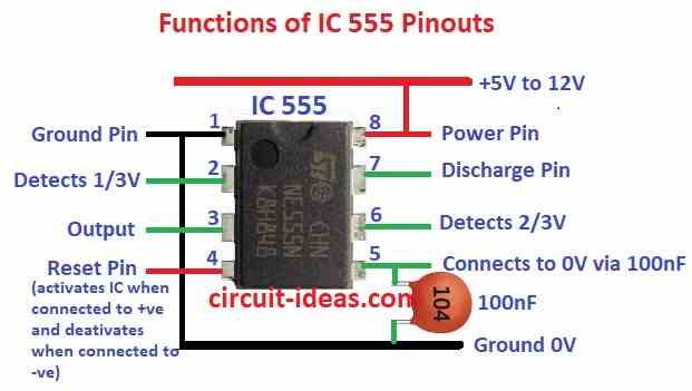
IC 555 Pinouts Functions:
- Draw the 555 timer as a rectangle.
- Label the pins according to their function instead of numbers and this will help you remember what each pin does.
IC 555 Internal Structural Layout:
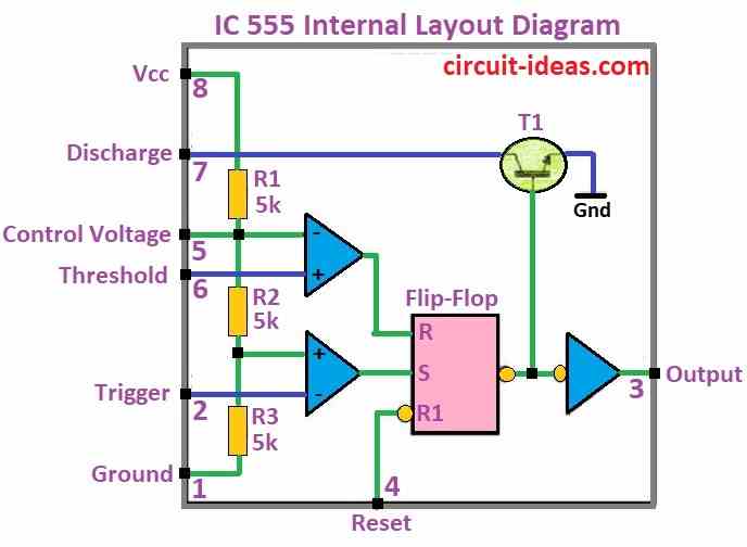
555 chip works with power between 16V and 18V.
Pin 3 (output) and pin 7 (discharge) which goes low together inside chip and resistor R1 makes pin 7 go high.
Chip gives current in two ways:
Push out (source): 100mA at 5V, 200mA at 15V
Pull in (sink): 50mA at 5V or 15V
Common problems:
Use more current with around 10mA.
Output voltage is little less than power which is up to 2.5V lower and output voltage is little more than ground which is 0.5 to 1.5V higher
It can also push 200mA but pulls only 50mA
Modes of use:
Astable: Chip turns ON and OFF again and again
Monostable: Chip turns ON for short time after trigger
VCO (Voltage Controlled Oscillator): Timing controlled by voltage signal
ASTABLE MULTIVIBRATOR
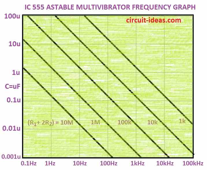
Below is a astable multivibrator frequency graph chart that can help us figure out how fast the 555 chip turns ON and OFF.
The 555 timer chip can act as a flasher that rapidly turns ON and OFF, also this ON–OFF rate is known as frequency.
We can also find frequency using special chart or formula.
Astable IC 555 using graph
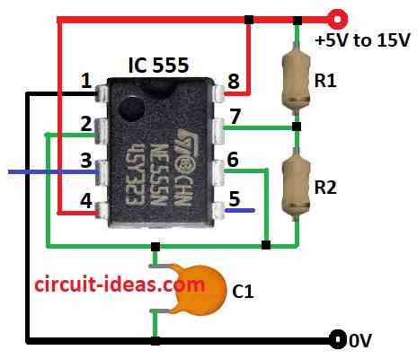
Chart works only for special circuit setup.
In this setup:
Capacitor charges slowly through two resistors R1 and R2.
When full enough pin 6 sees it and tells pin 7 to empty it fast and when empty enough, then pin 2 sees it and tells pin 7 to stop and then it start charging again.
Hence, this keeps repeating and flashes again and again.
A small resistor protects the chip; however, it does not affect the flashing speed.
How to use chart:
Add two resistors like time: 1 hr + 10 hr = 11 hr same for resistors
Find the total resistor value on resistor scale e.g.10,000 ohm = “1” on 10k scale
Draw straight line across chart from that point and then see where line meets our capacitor value like 0.1 microfarad
Finally, that point shows our flashing speed in hertz Hz
Formula:
There is also a simple math like formula to find flashing speed but chart is faster for quick guess.
Formula:
Frequency = 1.4 / [(R1 + 2×R2) × C]
where:
- R1 is the resistor in series with capacitor C
- R2 is the resistor in parallel with capacitor C
- C is the capacitor value
This formula helps in circuits that blink or flash like timers or LED blinkers and we can change R1, R2 or C to make blinking faster or slower.
IC 555 Astable Frequency table
| 555 astable frequencies | |||
| C | R1 = 1k R2 = 6k8 | R1 = 10k R2 = 68k | R1 = 100k R2 = 680k |
| 0.001µ | 100kHz | 10kHz | 1kHz |
| 0.01µ | 10kHz | 1kHz | 100Hz |
| 0.1µ | 1kHz | 100Hz | 10Hz |
| 1µ | 100Hz | 10Hz | 1Hz |
| 10µ | 10Hz | 1Hz | 0.1Hz |
Simple Astable
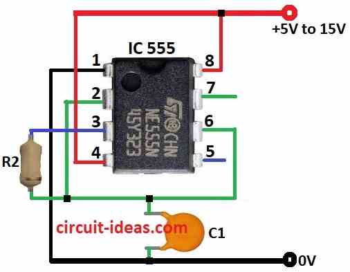
The simplest 555 flasher circuit needs only one resistor and one capacitor.
The chip uses pin 3 (output) to charge and discharge the capacitor and this makes the blinking (flashing) happen.
Formula:
When 555 timer is in astable mode it makes a continuous square wave like ON-OFF signal again and again , so we can find the frequency speed of blinking by using below formula:
f = 1.44 / [(R1 + 2×R2) × C]
where:
- f is the frequency in hertz Hz
- R1 is the resistor between pin 7 discharge and pin 6 threshold
- R2 is the resistor between pin 7 discharge and pin 3 output
- C is the capacitor between pin 5 control voltage and ground and also connected to pin 7
This design lets the 555 chip blink without stopping.
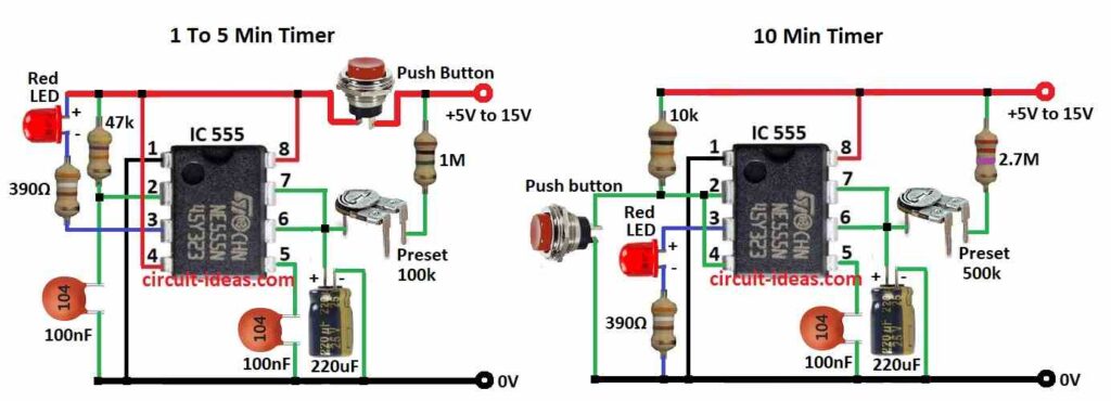
Low Frequency Oscillators
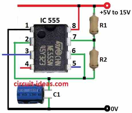
If we use a special capacitor called electrolytic capacitor instead of regular one then the flashing will slow down a lot.
When it flashes less than once per second then its not a flasher anymore but it becomes a timer or delay circuit.
Therefore, with this setup the 555 timer can make delays up to 30 minutes, but for long delays the timing is not very accurate.
Low frequency oscillator 555 delay time chart:
| 555 Delay Times: | |||
| C | R1 = 100k R2 = 100k | R1 = 470k R2 = 470k | R1 = 1M R2 = 1M |
| 10µ | 2.2sec | 10sec | 22sec |
| 100µ | 22sec | 100sec | 220sec |
| 470µ | 100sec | 500sec | 1000sec |
555 ASTABLE OSCILLATORS
555 timer chip is very useful and it we can make circuits that:
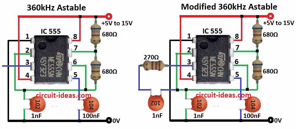
- Flash very fast up to 300,000 times per second or 300 kHz or gives long delays up to 30 minutes
But remember:
- Super fast flashing may not be stable and very long delays may not be exact
SQUARE WAVE OSCILLATOR
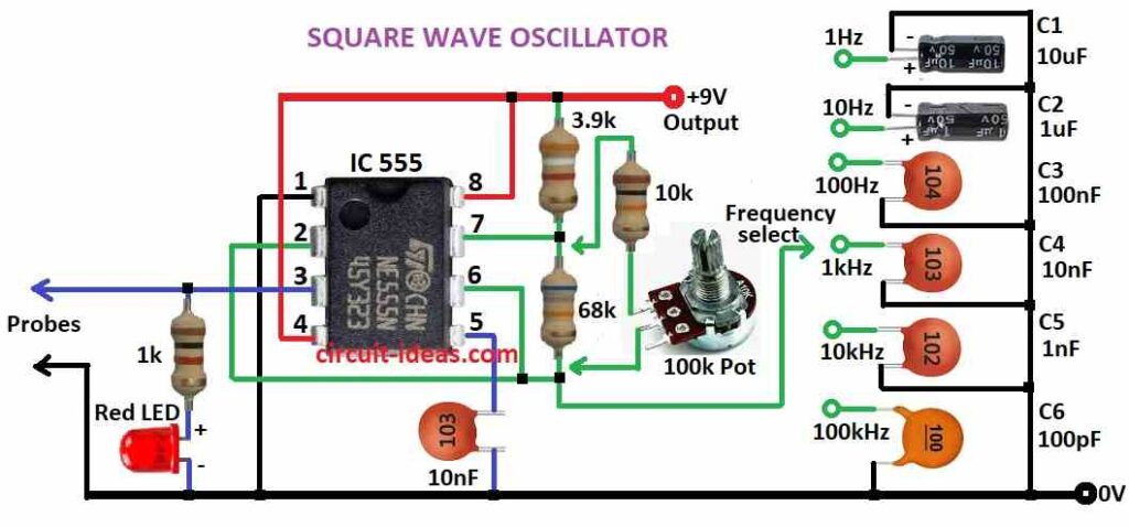
Astable Mode:
- The 555 timer works as a free-running oscillator and continuously generates square-wave ON-OFF pulses; moreover, the resistor and capacitor values show the oscillation frequency.
Monostable Mode:
- The 555 timer acts as a one-shot timer and a trigger pulse turns the output ON for a preset duration; afterward, the output turns OFF automatically and moreover, external components show the timing period.
Bistable Mode:
- The 555 timer acts like a flip-flop and behaves as a memory switch, one trigger turns the output ON, while another trigger turns it OFF.
- Moreover, it stays in each state until a new trigger changes it, just like a toggle switch.
555 Monostable or “one Shot”
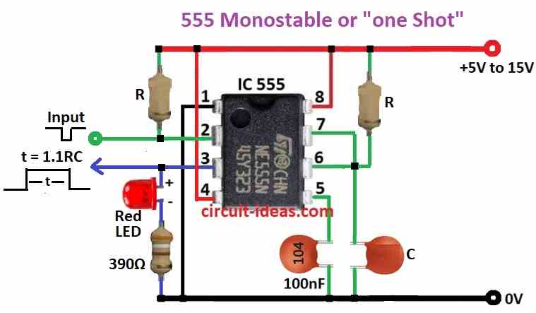
Monostable Configuration:
- In this setup the 555 timer works in one-shot mode using special resistor, capacitor and wiring.
Falling Edge Trigger:
- When a negative pulse like falling edge comes to pin 2 then output goes high to logic 1.
Set Duration T:
- The output stays high for a fixed time T; moreover, the resistor and capacitor values show this time period
One Shot Circuit:
- This design triggers one pulse per activation; therefore, engineers call it a “one-shot” circuit.
Conclusion:
Overall, Simple IC 555 Oscillator Circuits is a very popular because it is a versatile chip which is easy to use and works in many circuits like for blinking, timing or oscillating.
Furthermore, 555 timer chip is easy and useful it can make lights blink, sounds beep or delays to happen; as it just uses few parts like resistors and capacitors.
Also, this chip is good for learning and making fun projects.
Leave a Reply