Subwoofer Amplifier Circuit using IC TDA7294 is to boost low bass sound for subwoofer speaker, also the IC is an audio amplifier chip.
TDA7294 is one-chip IC in multiwatt 15 package and it is good for powered speakers, home stereo and big TVs., also it work as class AB amplifier for Hi-Fi sound.
Circuit Working:
Parts List:
| Components | Values | Quantity |
|---|---|---|
| Resistors (All resistors are 1/4 watt unless specified) | 22k | 3 |
| 680Ω | 1 | |
| 10k | 1 | |
| 2.7Ω | 1 | |
| Capacitors | Ceramic 100nF | 3 |
| Ceramic 470nF | 1 | |
| Electrolytic 22μF 25V | 2 | |
| Electrolytic 10μF 25V | 2 | |
| Electrolytic 1000μF 25V | 2 | |
| Semiconductors | IC TDA7294 | 1 |
| Heatsink IC TDA7294 | 1 | |
| ON/OFF Switch | 2 | |
| 8Ω 150 watt subwoofer speaker | 1 |
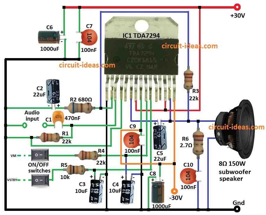
To begin with in the above circuit diagram we have used 150W subwoofer speaker with 8 ohm for best sound.
If only have 30V capacitors then use them, 50V is better but 30V okay, higher voltage capacitors work better and last longer.
Also, pins Vm and Vstby are for extra features, no need? just leave them not connected and be sure no voltage goes to those pins.
Then send music signal to non-inverting input pin of TDA7294 and for volume control put 10k ohm variable resistor between input pin and music source.
Moreover, this circuit is easy to make on breadboard and after building give it power with dual 30V power supply.
Formulas:
When making subwoofer amp with TDA7294 we should think about heat, speaker ohm, power supply and gain.
Need these parts and formulas:
Gain Calculation:
Gain changes with feedback resistors.
Use formula:
Gain(dB) = 20 × log10(Rf / Rin)
where,
- Rf is the feedback resistor
- Rin is the input resistor
Output Power Calculation:
Use formula:
Pout = (Vpeak)² / 2R
where,
- R is the speaker impedance with 8 ohm
- Vpeak is the voltage across speaker
Follow this information to build subwoofer amp with TDA7294 and change parts as needed.
How to Build:
To build a Subwoofer Amplifier Circuit using IC TDA7294 below mentioned are the steps for connections:
- First, get all parts like shown in circuit diagram.
- Next, pin 1 of IC1 connects to ground.
- Then pin 2 of IC1 connects to ground with capacitor C2 and resistor R2.
- After that, pin 3 of IC1 connects to audio input with capacitor C1 and also connect resistor R1 from pin 3 to ground.
- Now pin 4 of IC1 connects between ground and resistor R1.
- Then pin 6 of IC1 connects to one side of 8Ω speaker and other side of speaker connects to ground.
- Also, connect capacitor C5 positive side to pin 6 and negative side to speaker.
- Pin 7 and pin 13 connects to +30V power.
- Pin 8 connects to ground with capacitor C9 and pin 9 connect to ON/OFF switch VM through resistor R4.
- Then also, pin 10 connect to ON/OFF switch VSTBY through resistor R5.
- Next, pin 14 connects to pin 2 using resistor R3 and pin 15 connects to -30V power.
- After that, capacitor C4s positive connects to pin 9 and negative to ground and capacitor C3s positive connects to pin 10 and negative to ground.
- Then capacitor C8s negative connects to pin 15 and positive connects to ground and then capacitors C6s and C7s positive connects to ground.
- Lastly, resistor R6 and capacitor C10 connects from pin 6 to ground.
Safety Notes:
- Be careful and avoid touching live parts when the power is ON, as high voltage can cause serious injury.
- Insulate all wires and connections properly to prevent short circuits and reduce the risk of fire.
- TDA7294 gets hot so use big heat sink to keep it cool and pick power supply with correct current for our circuit.
Conclusion:
To conclude, this Subwoofer Amplifier Circuit using IC TDA7294 can give deep bass to our music system, also we should use right parts, keep it cool with heat sink and work in open air place.
Hence, if anyone is beginner then try small circuit first as safety is most important.
Leave a Reply