A Simple Voltage Follower Circuit using Op-amp IC 741 provides an output that matches the input; therefore, engineers also call it a buffer amplifier or a unity-gain amplifier.
IC 741 op-amp is cheap and useful that is why so many people use it.
Voltage follower has high input impedance and with low output impedance and it can give current to many loads and output; hence, there is no change, and also it take very little current from input like sensor.
Circuit Working:
Parts List:
| Components | Values | Quantity |
|---|---|---|
| Resistor | 1k 1/4 watt | 1 |
| Preset 10k | 1 | |
| Semiconductors | IC 741 | 1 |
IC 741 Op-Amp which is a Tiny Power Chip:
- IC 741 is a small 8-pin op-amp chip that designers use in many circuits; so, here, we will discuss a circuit that uses this IC.
Inputs and Outputs of IC 741:
- IC 741 has two input pins and pin 3 is non-inverting (+) and pin 2 is inverting (–).
- Pin 6 is output pin and it works with max 22V from battery or dual power.
Not Just Voltage Follower an IC 741 Does More:
- IC 741 is general op-amp not only for voltage follower, as it can work as comparator and compare voltages
- Multivibrator make wave signal, integrator add voltage, differentiator find voltage change speed and active filter passes only some frequencies
Voltage Follower Circuit an easy and useful:
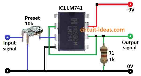
- Input signal goes to pin 3 (+)
- Pin 2 (–) connects back to output pin 6 and this connection provides feedback.
- Power come from battery to special pins and then output goes to resistor like R1 which is the load.
Why Use Voltage Follower?
- Big input impedance go up to 1 million ohm with small output impedance and this means the circuit take very small current from sensor/input but can give current to many loads; so signal does not loses strength.
Formulas:
Voltage Gain Formula for Voltage Follower Op-Amp like LM741.
Formula:
Av = Vo / Vin = 1
where:
- Av is the voltage gain
- Vo is the output voltage
- Vin is the input voltage
Note:
Voltage gain is 1 output voltage same as input voltage; why? because op-amp has very high gain, as it makes voltage at pin 2 (–) almost same as pin 3 (+).
Then resistor R1 connects pin 2 to output pin 6, so the output follows the input.
Ohms Law Relation Between Current, Voltage and Resistance:
Formula:
I = V / R
where:
- I is the current in amps like water flow in pipe
- V is the voltage in volts like water pressure
- R is the resistance in ohms Ω like narrow pipe slowing flow
Summary:
More voltage means more current and more resistance means less current.
Furthermore, ohms law works best in ideal condition and real circuits may change due to heat or other effects.
How to Build:
To build a Simple Voltage Follower Circuit using Op-amp IC 741 follow the below mentioned steps:
- First, collect all parts as shown in diagram.
- Next, connect pin 2 to pin 6 of IC 741 and also connect R1 to ground between pin 6 and output.
- Now, connect pin 3 to input signal using 10k preset.
- After that, connect pin 4 to ground.
- Also, connect pin 6 to output signal using resistor R1.
- Then connect pin 7 to +9V supply.
Safety Notes:
- Be safe while working with circuit and use correct voltage and good components and also follow general safety rules always.
Conclusion:
Overall, Simple Voltage Follower Circuit using Op-amp IC 741 is easy and useful, as it gives same output as input with no signal loss.
Moreover, high input impedance with no load on input and low output impedance can drive many loads; finally, it is good for many circuit uses.
Leave a Reply