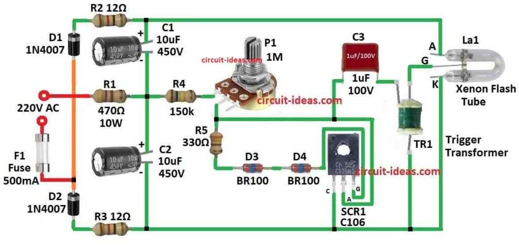
Xenon Tube Stroboscope Circuit show how to make flashing light using special xenon tube stroboscope.
It uses only few parts and can plug in normal 220V power socket to make light flash very bright!
WARNING: This circuit is used in high voltage and which can be dangerous
Better ask help from expert electrician.
This circuit is not good project for beginner.
What is a Xenon Tube Stroboscope Circuit:
Xenon Tube Stroboscope Circuit is electric circuit using xenon gas tube for making very bright flashing light.
Stroboscope is device that make short strong flash of light again and again.
This device is used for many thing like photo, machine checking and fun show.
Circuit Working:

Parts List:
| Component | Quantity |
|---|---|
| Resistors (All resistors are 1/4 watt unless specified) | |
| 12Ω | 2 |
| 470Ω 10W | 1 |
| 150k | 1 |
| Potentiometer 1M | 1 |
| Capacitors | |
| PPC 1μF 100V | 1 |
| Electrolytic 10μF 450V | 2 |
| Semiconductors | |
| SCR C106 | 1 |
| Diodes 1N4007 | 2 |
| Diac BR100 | 2 |
| Xenon flash tube | 1 |
| Trigger transformer | 1 |
| Fuse 500mA | 1 |
Xenon tube stroboscope is make very bright flashing light by using xenon gas tube with high voltage.
Potentiometer P1 must have nylon plastic shaft.
If metal part are touch it can be very dangerous and maybe even more deadly.
Main part of this device is U-shape xenon gas tube and this tube is filled with xenon gas which is safe gas.
Tube has three pins: anode, cathode and one ignition grid.
Diodes D1 and D2 with capacitors C1 and C2 make voltage doubler.
It can change low voltage to around 600V DC.
This 600V go between anode and cathode of tube.
Even xenon gas does not conduct electricity good but the 600V make strong electric field and this field make gas ionize near electrodes.
Then ions move to charged pins and small current flowing start.
To really start the flash ignition transformer TR1 give 5 to 10 kV to grid.
Transformer make big voltage by cutting current in primary coil fast using SCR1 which is the silicon rectifier.
When voltage on capacitor C2 reaches 500V and TR1s main resistor is low then capacitor C3 charge fast.
SCR turn ON when trigger diodes D3 and D9 goes over limit.
Then C3 discharge fast into TR1 and TR1 make big voltage in secondary coil.
This high voltage sparks the xenon tube and make bright flash.
Speed of charging C3 and how fast flash happen can change using potentiometer P1.
Resistor R1 on neutral line stop too much current.
If R1 is not there then fuse F1 can burn fast because tube during flash act like short circuit.
Good xenon tube use is 60 watt-second (60 Ws) which usually come with ignition transformer.
Anode pin is mostly marked with red dot.
Warning: This strobe circuit is connected direct to AC power which is very dangerous to touch when working.
Even after unplug capacitors inside may still have high voltage which can give big shock.
Always use plastic shaft and plastic knob on potentiometer and be safe!
Formulas:
Firing voltage of DIAC can be find using easy formula and the voltage VBO is given in DIAC datasheet.
This voltage is same like firing voltage Vf.
Formula to find firing voltage is:
Vf = VBO
where:
- Vf is firing voltage when DIAC start to conduct.
- VBO is breakdown voltage of DIAC.
Sometimes small difference happen in Vf because of how DIAC is made or how it used.
But mostly Vf and VBO are almost same.
How to Build:
To build a Xenon Tube Stroboscope Circuit following the below steps for connections process:
- For safety remove power before starting the work on circuit.
- Be sure all capacitors are empty means discharged.
- Put xenon gas tube in place and follow circuit diagram.
- Tube has anode, cathode and one ignition grid.
- Fix plastic nylon shaft to potentiometer P1 with no metal parts
- Connect diodes D1, D2, D3 and D9 and also capacitors C1, C2 and C3 same like circuit diagram shown.
- These parts help to double voltage and charge the capacitors.
- Voltage doubler circuit make DC voltage go up to around 600 volts.
- Check all parts value and connection are correct before continue.
- Connect ignition transformer TR1 in circuit.
- This give 5 to 10 kV high voltage to make xenon tube light up.
- Put SCR1 silicon controlled rectifier in place.
- This part cuts current fast and help make high voltage in transformer.
- Turn potentiometer P1 to control how fast capacitor C3 charge.
- This control how often xenon tube flash.
- Connect resistor R1 to neutral line and this part limits the current.
- Without R1 fuse F1 can blow fast because xenon tube act like short during flashing.
- Check all wires and parts match circuit diagram.
- Check values of all parts again before switching ON.
- When ready carefully connect circuit to power.
- See if xenon tube flash and light properly.
Safety Precautions for Testing:
- When power is ON do not touch any part!
- Use safety tools like gloves, goggles, etc
- If circuit does not work then turn OFF the power first.
- Then check all connections and parts again.
Note:
- This type of high voltage circuit is risky.
- If anyone is not having experience better ask expert help.
- Always think safety from beginning to end.
Conclusion:
Xenon Tube Stroboscope Circuit is special electric circuit that uses xenon gas tube to make fast bright flashing light.
All parts work together to make xenon gas ionize and give strong regular flash.
Leave a Reply