This 5 Watt LED Driver Circuit (SMPS) shows how to make power supply using wall plug to turn ON bright LEDs.
Also, it supports white LEDs but it works with blue, green, red, yellow and even UV light
What is a 5 Watt LED Driver Circuit:
A 5 Watt LED Driver Circuit powers a 5-watt LED light, providing steady current or voltage.
Since, LEDs require correct current or voltage to work properly and avoid damage, a special LED driver helps keep this balance.
Also, below is a simple diagram of a 5 watt LED driver circuit using a self-oscillating flyback converter which can run the LED directly from wall mains power with good efficiency.
Circuit Working:
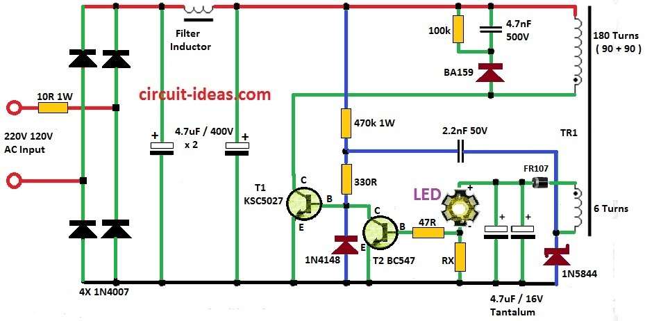
Parts List:
| Components | Values | Quantity |
|---|---|---|
| Resistors (All resistors are 1/4 watt unless specified) | ||
| 10Ω 1W MFR | 1 | |
| 470k 1W MFR | 1 | |
| 330Ω | 1 | |
| 100k | 1 | |
| 47Ω | 1 | |
| Rx = See text | 1 | |
| Capacitors | ||
| PPC 4.7nF 500V | 1 | |
| PPC 2.2nF 50V | 1 | |
| Electrolytic 4.7μF 400V | 2 | |
| Tantalum 4.7μF 16V | 2 | |
| Semiconductors | ||
| Diode 1N4007 | 4 | |
| Diode 1N4148 | 1 | |
| Fast diode BA159 | 1 | |
| Schottky diode 1N5844 | 1 | |
| Diode FR107 | 1 | |
| Transistor KSC5027 | 1 | |
| Transistor BC547 | 1 | |
| LED 5 Watt White | 1 | |
| Transformer (as given in article) | 1 | |
| Filter Inductor (as given in article) | 1 |
The main winding T1 work like power switch in power supply and this power supply work as flyback self-oscillating converter.
For this, we use KSC5027 transistor.
Also, shunt resistor Rx check the LED current in this current mode setup and this extra winding give feedback to system.
How to Calculate Resistor:
We used below formula to find value of Rx:
Rx = 0.65V / I
Here,
- I means needed current for LED.
If we change LED current then brightness can go up or down it can also help LED to live longer.
How to Make Transformer:
First, construct transformer Tr1 on an EE core taken from an old ATX PC power supply, the center part measures 4.5 × 4.5 mm
Primary winding has 180 turns of 0.2 mm wire and secondary winding has 6 turns of triple 0.5 mm wire.
Winding order is: first half of primary → then secondary → then rest half of primary.
Also, we can use ready-made transformer for 5V SMPS eliminating the need for an extra winding.
Adding Voltage Feedback:
Furthermore, if LED break or stops working then power supply should still be safe and so we should add voltage feedback in system.
Also, this help make system more accurate and safe.
Power Supply Frequency:
Power supply work at around 80 kHz and this high frequency make it more efficient for running an LEDs.
How to Build:
To Build a 5 Watt LED Driver Circuit (SMPS) following steps mentioned below for connection:
- First, wind the primary coil with 180 turns of wire which should be 0.2 mm thick.
- Then, make the secondary coil with 6 turns using triple 0.5 mm wire.
- Next, wind first 90 turns of primary and then wind secondary then finish with last 90 turns of primary.
- After that, put transistor like KSC5027 to act like power switch.
- Then, find the value of shunt resistor Rx using this formula: Rx = 0.65V / I where, I is current for LED.
- Also, connect this resistor Rx to check LED current.
- Then, use Schottky diode as rectifier because it gives better efficiency.
- After that, put all capacitors and resistors as shown in the circuit diagram.
Testing:
- Use a variable power supply to slowly increase power to the circuit.
- Watch the LED brightness and check output voltage and current with meter.
Warning:
- First, this circuit connects directly to high voltage mains of 220V so it is very dangerous and is not good for beginners.
- Also, capacitors can still hold dangerous voltage even after we turn the power OFF and the circuit may not fully isolate the LED from the mains
- Further, be very careful when touching the parts and do everything at ones own risk.
- Hence, the writer is not responsible if anything goes wrong or if there is any damage or injury.
Conclusion:
This 5 Watt LED Driver Circuit (SMPS) use simple parts and run directly from 220V AC and it gives steady power to LED with good efficiency.
But it connects to high voltage so build only if we have enough knowledge and always be careful.
Leave a Reply