This easy Motion Detector Circuit uses IC 555 to find human from far, as circuit have two parts:
Transmitter:
IC 555 work like astable multivibrator and it make square wave signal and this signal goes out through IR sensor (infrared).
Receiver:
Phototransistor see IR beam and if someone moves and block the beam then phototransistor work and turn ON IC 555.
Then output device turns ON like LED or alarm also this circuit need parts like IC 555, resistors, capacitors, IR sensor, phototransistor, LED or relay.
Circuit Working:
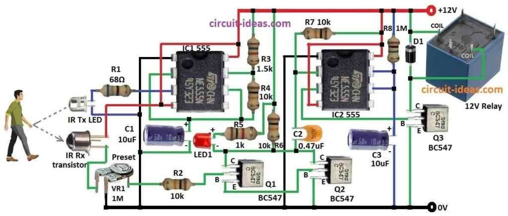
Parts List:
| Components | Values | Quantity |
|---|---|---|
| Resistors | 68Ω 1/4 watt | 1 |
| 1.5k 1/4 watt | 1 | |
| 1M 1/4 watt | 1 | |
| 1k 1/4 watt | 1 | |
| 10k 1/4 watt | 4 | |
| Preset 1M | 1 | |
| Capacitors | Ceramic 0.47μF | 1 |
| Electrolytic 10μF 50V | 2 | |
| Semiconductors | IC 555 | 2 |
| Transistors BC547 | 3 | |
| Diode D1 1N4007 | 1 | |
| LED any 5mm 20mA | 1 | |
| IR Transmitter Photodiode | 1 | |
| IR Receiver Phototransistor | 1 | |
| 12V Relay | 1 |
To begin with, infrared proximity detector is useful part in many automation systems, as we see it in auto water taps, hand dryers and some auto doors.
Also, this circuit use 555 IC to make short high voltage pulses and these pulses goes out as IR beams from LED.
Then IR beams focus on target area and if object come in front then beam reflect back, then phototransistor catch this reflected beam and it turn ON relay and alarm.
The relay remains ON for a period shown by the circuit components and to test the circuit, move our hand within 1 meter of the IR beam.
The circuit will then activate the relay and keep it on for a duration set by the 10 µF capacitor and the 1 MΩ resistor.
Finally, this shows circuit is working and we can use 1M preset to change how sensitive it is, which means how close object must be to start alarm.
Formula:
Important formula for frequency (f) in transmitter part of 555 motion detector:
f = 1.44 / (R3 + 2×R4) × C
where,
- R3, R4 and C1 connect with IC1 555 which work as astable multivibrator.
We can change motion detection sensitivity by changing IR pulse frequency, so use this formula to adjust frequency.
How to Build:
To build a Motion Detector Circuit using IC 555 follow below mentioned steps:
Connection of IC1:
- First, collect all parts shown in diagram.
- Next, connect pin 1 of IC1 555 to ground.
- Then connect pin 2 to pin 6 of IC1 and connect capacitor C1 from pin 2 and 6 to ground.
- Now connect pin 3 of IC1 to IR transmitter photodiode and then to ground through resistor R1.
- Connect pin 4 and pin 8 of IC1 to +12V supply.
- From +12V connect IR receiver phototransistor to first leg of preset VR1 in series.
- After that, connect resistor R4 between pin 6 and pin 7 of IC1 and also connect resistor R3 from pin 7 of IC1 to +12V.
Connection of IC2:
- First, connect pin 1 of IC2 555 to ground.
- Next, connect pin 2 to pin 6 of IC2 and connect resistor R7 from pin 2 to +12V.
- Then connect pin 3 of IC2 to base of transistor Q3.
- Now connect pin 4 and pin 8 of IC2 to +12V.
- After that, connect pin 6 to pin 7 of IC2, also connect capacitor C3 from pin 6 and 7 to ground.
- Also, connect resistor R8 from pin 7 to +12V.
- Then connect LED and resistor R5 in series from +12V to collector of Q1.
- Now connect collector of Q1 to collector of Q2, connect base of Q1 to first leg of preset VR1 through resistor R2 and then connect emitter of Q1 to ground.
- Also, connect base of Q2 to emitter of Q1, connect emitter of Q2 to ground and then connect collector of Q3 to +12V through diode D1.
- Lastly, connect base of Q3 to pin 3 of IC2 and emitter of Q3 to ground and then connect relay coil between +12V and diode D1 and second relay coil leg between D1 and Q3 collector.
Conclusion:
To conclude, this Motion Detector Circuit using IC 555 is easy and works well, as it sends IR pulses detects reflected light with phototransistor and turns ON alarm or relay when motion happens.
Also, it is useful in auto systems like security, taps and dispensers.
Leave a Reply