Automobile Brake Failure Indicator Circuit is backup system.
It tell driver if brake system have a problem.
It uses electric parts to check brake and if problem comes then it show light or make sound.
This circuit work only in cars with negative grounding.
It also give signal if brake switch does not work.
In cars with hydraulic brakes the brake switch on brake cylinder control back brake lights.
Brake switch work with fluid and if fluid leaks and pressure goes down then switch turns ON.
Only when big pressure loss happen then fluid leak is easy to see.
Each time brake used the circuit check brake switch and warn if brake may fail.
Circuit Working:
Parts List:
| Category | Item | Quantity |
|---|---|---|
| Resistors (All resistors are 1/4 watt unless specified) | 10k | 5 |
| 100k | 1 | |
| 470k | 1 | |
| 470Ω | 2 | |
| Capacitors | Ceramic 0.02μF | 1 |
| Ceramic 0.01μF | 1 | |
| Electrolytic 1000μF 25V | 2 | |
| Electrolytic 10μF 25V | 2 | |
| Electrolytic 100μF 25V | 1 | |
| Semiconductors | IC 77812 | 2 |
| IC 555 | 1 | |
| IC CA3140 | 1 | |
| LEDs red and green 5mm | 1 each | |
| Diodes 1N4007 | 2 | |
| Buzzer | 1 |
We can build this circuit on basic perfboard or normal PCB.
It uses op-amp IC CA3140 called IC2 to work like voltage comparator.
Another IC 555 timer called IC3 is used in monostable mode to give alarm signal for short time.
IC2 always check voltage across brake switch.
Two resistors give reference voltage to IC2s non-inverting input.
Inverting input get voltage from brake switch using diode, voltage regulator IC1, and one resistor.
When brake pedal is pressed then more voltage goes to inverting input.
If brake not pressed then IC2 output stays high with red LED1 is ON.
When brake pressed then voltage at inverting input changes and IC2 give low output and red LED1 turn OFF.
Also one small voltage pulse goes to IC3 through a capacitor.
IC3 555 give one pulse to about 1 second using resistor and capacitor.
This pulse turns ON the buzzer and LED2 for 1 second.
That beep and flash mean brakes are okay.
If brake system have problem like fluid leak and pressure drop then voltage does not change much when pressing brake.
Then IC2 does not gives signal and IC3 does not work with no buzzer and with no LED2.
So if red LED stays ON and no sound or flash then driver knows cars brake may have problem.
Formulas:
To make a monostable multivibrator circuit for car brake failure indicator using 555 IC uses this formula for pulse time T:
T = 1.1 × R × C
where:
- R is resistor R1 in ohms Ω
- C is capacitor in farads F
- 1.1 is a fixed value from 555 IC timing feature
This formula tell how long the output pulse will stay ON.
By using correct R and C values we can make good brake failure circuit.
Follow these steps and formula to build simple and working circuit with 555 IC in monostable mode.
This setup give a short beep and light flash if brake is working good.
If there is no beep or flash then brake may have problem.
How to Build:
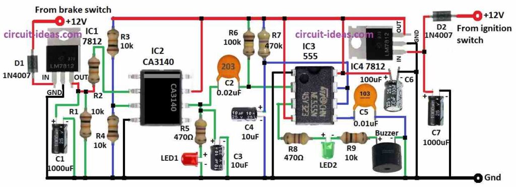
To build a Automobile Brake Failure Indicator Circuit follow the below mentioned steps for connections:
- Gather all parts from circuit diagram.
- Connect Vin pin of IC1 to +12V brake switch through diode D1.
- Connect GND pin of IC1 to ground.
- Connect Vout of IC1 to pin 2 of IC2 using resistor R2.
From Vout of IC1 connection:
- Capacitor C1 to ground
- Resistor R1 to ground
- Connect resistors R3 and R4 between +12V and ground.
- Connect pin 2 of IC2 to Vout of IC1.
- Connect pin 3 of IC2 between R3 and R4.
- Connect pin 4 of IC2 to ground.
- Connect pin 6 of IC2 to pin 2 of IC3 through capacitor C2.
From pin 6 of IC2 connection:
- Resistor R5 and LED1 to ground
- Capacitor C3 to ground between R5 and pin 6
- Connect pin 7 of IC2 to +12V.
- Connect resistor R6 between C2 and pin 2 of IC3.
- Connect resistor R7 and capacitor C4 between +12V and ground.
- Connect pin 1 of IC3 to ground.
- Connect pin 2 of IC3 to pin 6 of IC2.
- Connect pin 3 of IC3 to ground using R8, LED2, R9 and buzzer in series.
- Connect pin 4 and pin 8 of IC3 to +12V.
- Connect pin 5 of IC3 to ground using capacitor C5.
- Connect pin 6 and 7 of IC3 between R7 and C4.
- Connect Vin of IC4 to +12V from ignition switch through diode D2.
- Connect capacitor C7 from Vin of IC4 to ground.
- Connect GND of IC4 to ground.
- Connect Vout of IC4 to power IC2 and IC3.
Safety Tips:
- Circuit must work properly and if not then it may give wrong warning or no warning.
- Always test circuit well and use good parts.
- This system is not perfect but driver must know its limit.
- If red LED stay ON or with no buzzer sound then stop car safely and get brakes checked by mechanic.
Conclusion:
This DIY Automobile Brake Failure Indicator Circuit helps driver with light and beep if brake is not working well.
But expert should install it.
It can not replace brake service or careful driving.
It is just extra safety alert but not with full solution.
Leave a Reply