In washroom many time people forget to switch OFF the light because of this there is waste of electricity.
To solve this problem we can make a Auto On Off Light Circuit for Washroom.
When someone presses the switch it detects the presence and light will turn ON for some time and then get OFF automatically.
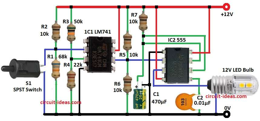
This project uses op amp LM741 and timer IC 555 with simple RC network to control timing.
Circuit Working:
Parts List:
| Component | Value | Quantity |
|---|---|---|
| Resistors (All resistors are 1/4 watt unless specified ) | 68k | 1 |
| 10k | 4 | |
| 50k | 1 | |
| 22k | 1 | |
| Capacitors | Electrolytic 470µF | 1 |
| Ceramic 0.01µF | 1 | |
| Semiconductors | Op-amp LM741 | 1 |
| Timer IC 555 | 1 | |
| Lamp 12V LED Lamp | 1 | |
| Switch SPST | 1 |
The circuit is built using two ICs LM741 op-amp and 555 timer.
Power supply is 12 volt DC and Switch S1 is used for input trigger and is normally closed SPST switch.
The Switch is fixed on wall and when the door is fully open and touches the wall the normally closed switch become open.
Op-amp LM741 is used as comparator.
When switch is open then inverting pin connect to 12V and non-inverting pin gets to around 4V.
Now non-inverting pin voltage is less than inverting pin so op-amp output give low logic.
This low logic goes to timer IC 555 input by divider.
Timer get trigger by low signal and give high output pulse.
Timer is in monostable mode and lamp get 12V from timer output and glow.
When person goes out and door closes then switch come back to normal closed position.
Now non-inverting pin voltage is higher than inverting pin.
Op-amp output become high logic and this cannot trigger timer.
So timer give no output and lamp turns OFF.
Formulas:
For monostable 555 timer ON time is given by:
T = 1.1 * R * C
here,
- T is the output pulse duration in seconds
- R is the resistor value in ohms Ω
- C is the capacitor value in farads F
Use values as from circuit diagram:
R = R7 = 10kΩ = 10,000Ω
C = C1 = 470µF = 0.000470F
Calculation:
10,000 × 0.000470 = 4.7
1.1 × 4.7 = 5.17
T = 5.17 seconds lamp stays ON about 5.2 seconds after trigger
How to Build:
To build a Auto On Off Light Circuit for Washroom following are the steps we need to follow for connections:
- Gather all the parts as shown in circuit diagram
- Connect op-amp IC1 LM741 pin 2 non inverting pin to the junction of resistor R1 and R2 and switch S1
- Non inverting pin 3 of op-amp IC1 LM741 connects between resistor R3 and R4
- Connect pin 4 of op-amp IC1 LM741 to GND of the circuit
- Connect pin 6 of op-amp IC1 LM741 to the junction of resistor R5 and R6 and pin 2 of IC2 555 timer
- Connect pin 7 of op-amp IC1 LM741 to VCC of 12V positive supply.
- Connect pin 1 of IC2 555 to GND of the circuit
- Connect pin 3 of IC2 555 to one end of lamp 12V 10 watt and other end of lamp connect to GND of the circuit
- Connect pin 4 and pin 8 of IC2 555 timer to 12V VCC positive supply
- Connect pin 5 of IC2 555 to capacitor C2 one end and other end of C2 goes to GND
- Connect pin 6 and pin 7 of IC2 555 between resistor R7 and one end of capacitor C1 and other end of C1 goes to GND
Conclusion:
This Auto On Off Light Circuit for Washroom is cheap and simple and make.
It saves energy because lamp turns OFF automatically after some time.
Only few components needed like LM741 op amp, 555 timer, resistors and capacitors.
By changing RC values and delay we can adjust according to our need.
Leave a Reply