With this easy guide for Simple Christmas Fairy Flashing LED Lights Circuit we are ready to jingle all way!
Also, this circuit makes fun and happy pattern with blinking LED lights which look like small Christmas bulbs and also to make lights look more special we can put them in line or shape and use different color bulbs too.
Circuit Working:
Parts List:
| Compoenets | Values | Quantity |
|---|---|---|
| Resistors | 1k 1/4 watt | 1 |
| 100Ω 1/4 watt | 1 | |
| Semiconductors | Transistor BC547 | 1 |
| D1 Multicolor fleshing LED | 1 | |
| D2 to D7 5mm 20mA LEDs | 6 |
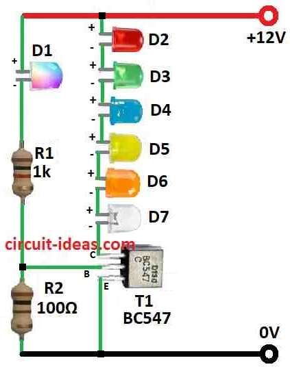
To begin with, this is an easy and cheap circuit not only for Christmas time, as it uses only two resistors, one blinking LED, small signal transistor like BC547 and many normal LEDs.
Furthermore, the other LEDs turn ON and OFF by transistor and the transistor work because blinking LED act like oscillator.
Also, we can use 12V unregulated power from mains as power source, because LED total voltage drop is near to 12V with no need for current limiting resistor.
For example if we use red LEDs with 1.65V drop then we can use 7 LEDs with 12V; or we can use 5 green LEDs with 2.7V each or 6 yellow LEDs with 2.1V each.
Lastly, we can also mix LED colors and it will look like fairy lights which appear very nice.
Formulas:
To make a circuit where LEDs blink one by one like Christmas fairy lights then this simple design uses resistors and one BC547 transistor to control LEDs.
How to Find Current for LEDs:
Most important is to keep LED safe and these LED should not get too much current and for that we must calculate resistor for each LED.
Formula to find LED current:
I = (Vsupply − VLED) / RLED
where:
- I is current in amperes
- Vsupply is our power voltage
- VLED is LED voltage drop which is normally around 2V but need to check datasheet
- RLED is resistor value in ohms
How to check resistor power:
We do not want resistor to get too hot for that we have used this formula:
P = I² × R
where:
- P is power in watts W
- I is current in amperes A
- R is resistance in ohms Ω
Finding Base Resistor for Transistor:
To make transistor BC547 work well we must give enough current to base pin, then we can use this formula:
RB = (Vsupply − VBE) / IB
where:
- VBE is base emitter voltage which is normally 0.7V for BC547
- IB is base current and it is IC / hFE
- IC is collector current
- hFE is gain of transistor
Use correct LED voltage, power supply and adjust resistor value to keep circuit safe and working good, as these formulas help us to make safe and working light circuit.
How to Build:
To build a Simple Christmas Fairy Flashing LED Lights Circuit follow the below mentioned steps:
Make the Base Circuit:
- First, connect the blinking LED to the circuit and this blinking LED will work like oscillator.
- Then connect this part to small BC547 transistor and the blinking LED turns the transistor ON and OFF.
Connect the Normal LEDs:
- Now connect the normal LED string to the transistor and this transistor will work like switch and it will turn ON and OFF the LEDs when the blinking LED flash.
Power Connection:
- Also, use 12V unregulated power from mains to run the circuit and be sure the power wires connect correct way.
No Need for Resistor:
- Because LED total forward voltage is same like power supply of 12V where there is no need of current limiting resistor.
Choose LED Colors Right Way:
- Choose LED color and number by checking their voltage drop, for example: Red LED (1.65V) → use 7 LEDs with 12V, Green LED (2.7V) → use 5 LEDs, Yellow LED (2.1V) → use 6 LEDs
Test the Circuit:
- After finish building, turn ON the power and see if the LEDs flash nice and proper.
Be Careful:
- Also, when working with electric, always take care and check all wires and parts again and if anyone is not sure ask someone who know or check book or video for help.
Conclusion:
To conclude, if we add one PNP transistor with NPN transistor we can make two LED lines blink alternately, which will look more beautiful and bright for Christmas time!
Moreover, this Simple Christmas Fairy Flashing LED Lights Circuit is fun DIY idea for holiday which is easy to build nice to see.
Leave a Reply