This Smoke Alarm Circuit is like house that has got a big nose.
This circuit smells smoke in air and if smoke come it make loud alarm sound.
Alarm can be buzzer, blinking light or it can be other alarm to start also.
Smoke detector can work in different way one can use small light like photoelectric or some use other small radioactive thing like ionization as both do not like smoke.
Main thing in this circuit is that it helps keep us safe and it tells there is fire going to happen.
Circuit Working:
Parts List:
| Category | Item | Quantity |
|---|---|---|
| Resistors (All resistors are 1/4 watt unless specified) | 1k | 2 |
| 100k, 100Ω, 220Ω | 1 each | |
| Preset 1M | 2 | |
| Capacitors | Electrolytic 100μF 25V | 2 |
| Electrolytic 4.7μF 25V | 2 | |
| Semiconductors | Transistors BC547 | 2 |
| FET BS170 | 1 | |
| SCR BT169 | 1 | |
| LED Red 5mm 20mA | 1 | |
| Optocoupler H21A1 | 1 | |
| Buzzer | 1 |
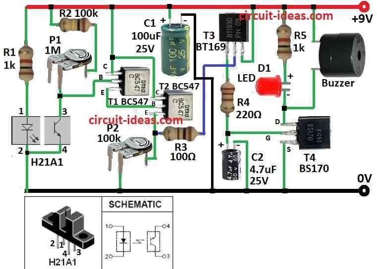
This smoke alarm circuit uses one part called H21A1 and it is a small box with one light (infrared LED) and one receiver (phototransistor) inside.
Between them there is small gap and when smoke goes inside a gap it block the light.
When there is no smoke the light goes to receiver and everything stays OFF.
But if smoke appears it stop the light and this changes output from ON to OFF.
Then the receiver stop working and two transistors T1 and T2 start working together like one strong switch like darlington pair
This makes voltage go to another part called SCR which is BT169 T3 and it turn ON.
After that power go to one more part that is MOSFET BS170 T4 and then the buzzer start making sound.
Also small light that is LED D1 turns ON to show alarm is working.
Buzzer makes noise until it is removed from 9V battery or power off.
If one wants better working then can adjust trimpots P1and P2 and change resistor R1 a little.
Formulas:
To make smoke alarm circuit we need use some basic formula from electronics which help to find right value for resistor, capacitor and other parts.
Here are some important formula we can use:
1. Resistor and Capacitor Values:
Voltage Divider Formula:
Use this to get smaller voltage from big voltage:
Vout = Vin × R2 / (R1 + R2)
where,
- Vin = input voltage
- R1, R2 are the resistor values
- Vout is the output voltage we want
2. Charging and Discharging of Capacitor of Time Delay:
Time constant: τ = R × C
where,
- τ (tau) is how fast capacitor charge or discharge
- R is the resistance in ohms
- C is the capacitance in farads
3. Capacitor Voltage Over Time for RC Charging:
V(t) = Vin × (1 − e^(-t / RC))
where,
- V(t) is the voltage at time t
- Vin is the input voltage
- e is the 2.718 which is the natural log
- t is the time
- R is the resistor
- C is the capacitor
This formula show how voltage builds up in capacitor over time.
4. Transistor Base Current for NPN like BC547:
IB = (Vin − VBE) / RB
where,
- VBE is the base to emitter voltage for around 0.7V for silicon transistor
- RB is the base resistor
- IB is the base current
5. Collector Current:
IC = β × IB
where,
- IC is the current going out of transistors collector
- IB is the base current
- β is the transistor gain for how much it multiply the current
With these formula we can choose parts we already have and test the smoke alarm circuit to be sure it works good.
How to Build:
To build a Smoke Alarm Circuit please follow the below mentioned circuit assembling steps:
- Look at circuit diagram and see how parts connect.
- Be sure H21A1 module is put in right way and LED on one side and phototransistor on other side of smoke gap.
- Connect H21A1 to other parts same like in diagram.
- Join transistors T1, T2, T3, T4 in darlington pair way.
- Connect SCR T3 after darlington output.
- Connect MOSFET T4 to gate pin of SCR.
- Change trimpots P1 and P2 and resistor R1 to get better working.
- These parts help control sensitivity which we can set them based on our needs.
- Give power using 9V DC battery or adapter.
- Now put little smoke in front of sensor slot.
- See if LED D1 light up and buzzer makes sound.
- If it does not work good then adjust again to fix sensitivity.
- When everything works okay then fix circuit in place where we want to detect smoke.
- Making this circuit need basic electronics knowledge.
- If we do not know much then its better to ask help from someone who know electronics and can build it safely.
Conclusion:
Smoke alarm circuit is very important safety device.
It find smoke in air and turn ON an alarm to tell people there is danger.
It uses sensor and small signals to check smoke and when smoke is found it makes loud sound.
This help people leave place fast and stop fire early which can save life and protect home.
Leave a Reply