This smart Battery Charger Circuit using a Solar Panel and 220V Supply charges the battery using sun and normal electricity.
During daytime solar panel take sunlight and charge the battery.
No worry if sky is cloudy or if it is night time it also uses normal 220V electricity to charge.
Also it has hot backup battery like smoke alarm one, so that the system still work even if there is no sun for many days.
With this the battery will always have power, if whatever happen to the weather .
Circuit Working:
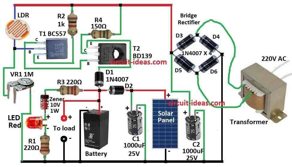
Parts List:
| Category | Item | Quantity |
|---|---|---|
| Resistors | 1k, 150Ω 1/4 watt | 1 each |
| 220Ω 1/4 watt | 2 | |
| Preset 1M | 1 | |
| LDR | 1 | |
| Capacitors | Electrolytic 1000μF 25V | 2 |
| Semiconductors | Transistors BC557, BD139 | 2 |
| Diodes 1N4007 | 2 | |
| Bridge Rectifier 1N4007 | 4 | |
| LED Red 5mm 20mA | 1 | |
| Zener diode 10V 1W | 1 | |
| Battery as per the load specification | 1 | |
| Solar Panel as per battery specification | 1 | |
| Transformer as per battery specification | 1 |
Solar Power Source:
In daytime the load is connected to devices and get power from solar panel or battery.
If sun is not strong enough then the battery help to give power.
One small solar cell give about 0.5V and 50mA power and when sun is bright its around 45mW.
To make 12V panel 24 such solar cells join in line which can give 1A current when sun is good.
In this circuit we use 12V 5W solar panel as it gives around 300mA which is enough to charge battery and run security system.
DC Power Source:
At night the charging is done with 12V DC and this come from step-down transformer 0-12V 1A and four diodes D3 to D6 making full wave rectifier.
Capacitor C2 cleans the power and removes the ripples so that battery and system get smooth DC.
Resistor R4 gives small current 80mA for night time with slow charging which is called trickle charging).
Battery gives power to security system at night.
This saves electricity and stop battery from too much charge, since daytime it already gives enough power.
This part show battery and solar voltage.
Zener diode turn ON the red LED only when battery is more than 11.6V.
If battery drop below 11V its LED goes OFF
In LED if there is no light then maybe battery might not be full or solar panel may not give 12V.
LDR Switch:
This part control night power.
In day LDR see light and give low resistance.
So transistor T1 PNP stay OFF with T2 also goes OFF
At night LDR get dark with resistance high and this makes base of T1 connects negative and so T1 and T2 turn ON.
Then current flow from T2 to battery and R4 limits it to 80mA for safe night charging.
VR1 can be turn to set how sensitive LDR is to light.
Battery Charger Setup:
Make this circuit on general PCB board and put it in safe case.
LDR should face sunlight and it should place solar panel in sunny area.
Before that connect battery and charge it full with normal charger.
Formula:
How to Choose Right Solar Panel for Charging Battery
When we pick solar panel many things matter like battery size (capacity), how much power panel it gives and the place where system work.
Here is easy steps with formula:
1. Find How Much Charging Current we Need:
For lead acid battery there is no need of full power we can charge with small current with around 10% to 20% of battery capacity.
For that we should use this formula:
Icharge = 0.1 × Cbattery
where,
- Icharge is the charging current in amps
- Cbattery is the battery capacity in Ah
This gives a safe guess.
We can change 0.1 number if battery maker say different.
2. Find Solar Panel Size (Power in Watts):
Solar panels give power in watts (W).
To find how big panel we need use the following formula:
Psolar = Icharge × Vsolar
where,
- Psolar is the solar panel power in watts
- Icharge is the charging current from step 1
- Vsolar is the solar panel voltage which is usually 12V or 24V
Example:
If battery is 10Ah then
Icharge = 0.1 × 10 = 1A
If solar panel is 12V then
Psolar = 1A × 12V = 12W
So we need 12W panel or a bit more for safety.
Note:
Use these steps to choose right solar panel for the battery.
But actual circuit may need change, maybe more sun or less and maybe battery may use more power.
So adjust if needed.
How to Build:
To build a Battery Charger Circuit using a Solar Panel and 220V Supply we need to follow the below mentioned steps:
How to Connect the Circuit:
- First connect solar panel to battery using diode D2 1N4007.
- This stop power from going back from battery to panel at night.
- Then connect transformer output to bridge rectifier diodes D3 to D6.
- After that connect to capacitor C2 to clean the DC power.
- Now connect battery to load whatever device we want to power.
- Put Zener diode across battery as this check battery voltage.
- Connect LEDs to Zener diode, they show battery status if ON it is full and if OFF it is low.
- Connect LDR to base of T1 and then connect collector of T1 to base of T2, this part will turn ON transformer power at night.
- Take one pin of VR1 variable resistor and connect it to LDR and other pin to ground.
Extra Things to Do:
- Place LDR where it can see sunlight in day and become dark at night.
- Turn VR1 to set how much light makes it switch.
- Put all parts in good case and be sure transformer gets air so it does not get too hot.
- Working with electric is risky.
- Only build this if one knows how to build and use safe tools with no wet hands and no water around.
- If not sure ask expert or someone who know well about electronics.
Conclusion:
In this Battery Charger Circuit using a Solar Panel and 220V Supply we should keep in mind, when we work with high voltage we should always be careful.
Use tools with insulation and work in dry place and never touch live wires.
If anyone is not having good experience with electronics better to ask expert or someone who knows it well for help .
Follow safety first always!